
User manual
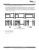
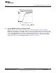

2 Ps/DIV
I
F
200 mA/Div
DIM
5V/Div
www.ti.com
External MOSFET Dimming and Contrast Ratio
Figure 11. t
D
and t
SU
(DIM Pin)
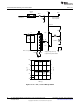
15 External MOSFET Dimming and Contrast Ratio
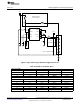
MOSFET Q4 and its drive circuitry are provided on the demonstration PCB (see Figure 12). When
MOSFET Q4 is turned on, it shorts LED+ to LED-, therefore redirecting the inductor current from the LED
string to the shunt MOSFET. The LM3402 / 04 is never turned off, and therefore become a perfect current
source by providing continuous current to the output through the inductor (L1). A buck converter with an
external shunt MOSFET is the ideal circuit for delivering the highest possible contrast ratio. For typical
delays and rise time for external MOSFET dimming, see Figure 13 - Figure 15.
19
SNVA342E–July 2008–Revised April 2013 AN-1839 LM3402/LM3404 Fast Dimming and True Constant LED Current
Evaluation Board
Submit Documentation Feedback
Copyright © 2008–2013, Texas Instruments Incorporated