
User manual

T
D
t
D
t
SD
t
D
t
SU
t
SD
t
D
t
SU
t
SD
D
MIN
D
MAX
T T
DIM
I
F
f
PWM
T =
1
T
t
D
+ t
SU
D
MIN
=
T
T - t
SD
D
MAX
=
t
SU
Contrast Ratio Definition
www.ti.com
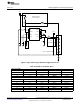
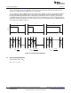
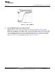
For illustrations, see Figure 10. The interval t
D
represents the delay from a logic high at the DIM pin to the
onset of the output current. The quantities t
SU
and t
SD
represent the time needed for the LED current to
slew up to steady state and slew down to zero, respectively.
As an example, assume a DIM duty cycle D
DIM
equal to 100% (always on) and the circuit delivers 500mA
of current through the LED string. At D
DIM
equal to 50% you would like exactly ½ of 500 mA of current
through your LED string (250 mA). This could only be possible if there were no delays (t
D
) between the
on/off DIM signal and the on/off of the LED current. The rise and fall times (t
SU
and t
SD
) of the LED current
would also need to be eliminated. If we can reduce these times, the linearity between the PWM signal and
the average current will be realized.
Figure 10. Contrast Ratio Definitions
14 Contrast Ratio Definition
Contrast Ratio (CR) = 1/D
MIN
D
MIN
= (t
D
+ t
SU
) x f
DIM
18
AN-1839 LM3402/LM3404 Fast Dimming and True Constant LED Current SNVA342E–July 2008–Revised April 2013
Evaluation Board
Submit Documentation Feedback
Copyright © 2008–2013, Texas Instruments Incorporated