
User manual

V
OUT
x t
D
L
+
0.20V
k x R
ON
2L
-
R
SNS
I
F
=
R
SNS
=
V
OUT
x t
D
L
(I
F
) -
0.20V
k x R
ON
2L
+
www.ti.com
Dimming
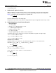
Calculate R
SNS
(42)
• V
OUT
= 13.8V
• V
IN
= 48V
• I
F
= 500 mA
• t
D
= 220 ns
• η = 0.85
• L = 100 µH
R
SNS
= 488 mΩ
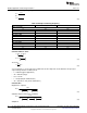
Calculate Average Current through LED
(43)
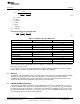
Table 11. Example 4 Average LED Current
V
IN
(V) V
OUT
(V) I
F
(A)
Three Series LEDs
36 10.4 0.507
48 10.4 0.507
60 10.4 0.507
Four Series LEDs
36 13.8 0.500
48 13.8 0.500
60 13.8 0.500
Five Series LEDs
36 17.2 0.493
48 17.2 0.493
60 17.2 0.493
In the reduced frequency application you can see that there is a difference of 14 mA between the low and
high of the average current.
If the original t
ON
circuit was used (no PNP transistor) with the switching frequency centered around 500
kHz the difference between the high and low values would be about 67 mA.
12 Dimming
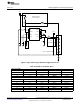
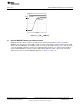
The DIM pin of the LM3402/04 is a TTL compatible input for low frequency pulse width modulation (PWM)
dimming of the LED current. Depending on the application, a contrast ratio greater than what the
LM3402/04 internal DIM circuitry can provide might be needed. This demonstration board comes with
external circuitry that allows for dimming contrast ratios greater than 50k:1.
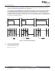
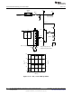
13 LM3402/04 DIM Pin Operation
To fully enable and disable the LM3402 / 04, the PWM signal should have a maximum logic low level of
0.8V and a minimum logic high level of 2.2V. Dimming frequency, f
DIM
, and duty cycle, D
DIM
, are limited by
the LED current rise time and fall time and the delay from activation of the DIM pin to the response of the
internal power MOSFET. In general, f
DIM
should be at least one order of magnitude lower than the steady
state switching frequency in order to prevent aliasing.
17
SNVA342E–July 2008–Revised April 2013 AN-1839 LM3402/LM3404 Fast Dimming and True Constant LED Current
Evaluation Board
Submit Documentation Feedback
Copyright © 2008–2013, Texas Instruments Incorporated