
User manual

V
OUT
V
IN
x K
t
OFF
= t
ON
- 1
V
IN
- V
OUT
k
R
ON
= t
ON
V
IN
- V
OUT
R
ON
t
ON
= k x
Modified COT Application Circuit
www.ti.com
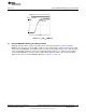
In this application you can see that there is a difference of 63 mA between the low and high of the
average LED current.
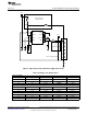
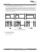
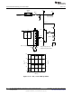
9 Modified COT Application Circuit
With the addition of one pnp transistor and one resistor (Q1 and R3) the average current through the
LEDs can be made to be more constant over input and output voltage variations. Refer to page one,
Figure 1. Resistor R
ON
(R2) and Q1 turn the t
ON
equation into:
(27)
Ignore the PNP transistor’s V
BE
voltage drop.
Design to the same criteria as the previous example with the improved application and compare results.
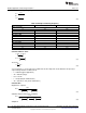
10 Modified Application Circuit Design Example 3
Design Example 1
• V
IN
= 48V (±20%)
• Driving 3, 4, or 5 HB LEDs with V
F
= 3.4V
• I
F
= 500 mA (typical application)
• Estimated efficiency = 82%
• f
SW
= fast as possible
• Design for typical application within t
ON
and t
OFF
limitations
The inductor, R
ON
resistor, and the R
SNS
resistor are calculated for a typical or average design.
• V
OUT
= 3 x 3.4V + 200 mV = 10.4V
• V
OUT
= 4 x 3.4V + 200 mV = 13.8V
• V
OUT
= 5 x 3.4V + 200 mV = 17.2V
Calculate t
ON
, t
OFF
and R
ON
Minimum ON time occurs when V
IN
is at its maximum value, and V
OUT
is at its lowest value.
Calculate R
ON
at V
IN
= 60V, V
OUT
= 10.4V, and set t
ON
= 300 ns:
(28)
R
ON
= 111 kΩ (113 kΩ) t
ON
= 306 ns
Check to see if t
OFF
minimum is satisfied.
At V
IN
= 36V, V
OUT
= 17.2V, and R
ON
= 113 kΩ calculate t
ON:
.
t
ON
= 806 ns
(29)
t
OFF
= 577 ns (satisfied)
12
AN-1839 LM3402/LM3404 Fast Dimming and True Constant LED Current SNVA342E–July 2008–Revised April 2013
Evaluation Board
Submit Documentation Feedback
Copyright © 2008–2013, Texas Instruments Incorporated