
Datasheet
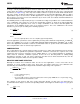

2.9V - 4.2V
LM3224
L
4.7 PH
C
C
2.2 nF
D
R
C
2k
C
IN
22 PF
C
OUT
10 PF
ceramic
R
TORCH
6.2:
(200 mA)
SHDN
3
V
IN
6
SW
5
FSLCT
7
FB
2
GND
4
V
C
1
Battery or
Power Source
SS
8
High Current
White LED
Pull high for TORCH.
Pull Flash Enable high
for FLASH.
R
FLASH
2.55:
(500 mA)
Torch
Enable
Flash
Enable
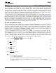
2.9V - 4.2V
LM3224
L
4.7 PH
C
C
2.2 nF
D
R
C
2k
C
IN
22 PF
C
OUT
10 PF
ceramic
R
SET
1.8:
(700 mA)
SHDN
3
V
IN
6
SW
5
FSLCT
7
FB
2
GND
4
V
C
1
Battery or
Power Source
SS
8
High Current
White LED
Pull high for FLASH or
constant full current,
PWM for TORCH or
partial current.
Optional
Disconnect
FET
LM3224
www.ti.com
SNVS277C –DECEMBER 2004–REVISED MARCH 2013
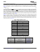
The 23V output is realized with a series of capacitor charge pumps. It consists of four stages: the first stage
includes C4, D4, and the LM3224 switch; the second stage uses C5, D5, and D1; the third stage includes C6,
D6, and the LM3224 switch; the final stage is C7 and D7. In the first stage, C4 charges to 8V when the LM3224
switch is closed, which causes D5 to conduct when the switch is open. In the second stage, the voltage across
C5 is VC4 + VD1 - VD5 = VC4 ≊ 8V when the switch is open. However, because C5 is referenced to the 8V
output, the voltage at C5 is 16V when referenced to ground. In the third stage, the 16V at C5 appears across C6
when the switch is closed. When the switch opens, C6 is referenced to the 8V output minus a diode drop, which
raises the voltage at C6 with respect to ground to about 24V. Hence, in the fourth stage, C7 is charged to 24V
when the switch is open. From the first stage to the last, there are three diode drops that make the output voltage
closer to 24 - 3xVDIODE (about 22.8V if a 0.4V forward drop is assumed).
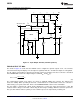
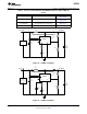
Figure 24. PWM White LED Flash/Torch Driver
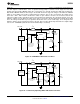
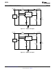
Figure 25. Continuously Operating White LED Flash/Torch Driver
Copyright © 2004–2013, Texas Instruments Incorporated Submit Documentation Feedback 17
Product Folder Links: LM3224