
Datasheet

f
PC
=
1
2S(R
C
+ R
O
)C
C
(in Hz)
(in Hz)
RHPzero =
V
OUT
(D')
2
2S,
LOAD
L
f
Z1
=
1
2SR
ESR
C
OUT
(in Hz)
f
P1
=
1
2S(R
ESR
+ R
L
)C
OUT
(in Hz)
LM3224
SNVS277C –DECEMBER 2004–REVISED MARCH 2013
www.ti.com
INPUT AND OUTPUT CAPACITOR SELECTION
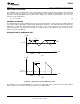
The switching action of a boost regulator causes a triangular voltage waveform at the input. A capacitor is
required to reduce the input ripple and noise for proper operation of the regulator. The size used is dependant on
the application and board layout. If the regulator will be loaded uniformly, with very little load changes, and at
lower current outputs, the input capacitor size can often be reduced. The size can also be reduced if the input of
the regulator is very close to the source output. The size will generally need to be larger for applications where
the regulator is supplying nearly the maximum rated output or if large load steps are expected. A minimum value
of 10µF should be used for the less stressful condtions while a 22µF to 47µF capacitor may be required for
higher power and dynamic loads. Larger values and/or lower ESR may be needed if the application requires very
low ripple on the input source voltage.
The choice of output capacitors is also somewhat arbitrary and depends on the design requirements for output
voltage ripple. It is recommended that low ESR (Equivalent Series Resistance, denoted R
ESR
) capacitors be used
such as ceramic, polymer electrolytic, or low ESR tantalum. Higher ESR capacitors may be used but will require
more compensation which will be explained later on in the section. The ESR is also important because it
determines the peak to peak output voltage ripple according to the approximate equation:
ΔV
OUT
≊ 2Δi
L
R
ESR
(in Volts) (14)
A minimum value of 10µF is recommended and may be increased to a larger value. After choosing the output
capacitor you can determine a pole-zero pair introduced into the control loop by the following equations:
(15)
where
• R
L
is the minimum load resistance corresponding to the maximum load current (16)
The zero created by the ESR of the output capacitor is generally very high frequency if the ESR is small. If low
ESR capacitors are used it can be neglected. If higher ESR capacitors are used see the High Output Capacitor
ESR Compensation section. Some suitable capacitor vendors include Vishay, Taiyo-Yuden, and TDK.
RIGHT HALF PLANE ZERO
A current mode control boost regulator has an inherent right half plane zero (RHP zero). This zero has the effect
of a zero in the gain plot, causing an imposed +20dB/decade on the rolloff, but has the effect of a pole in the
phase, subtracting another 90° in the phase plot. This can cause undesirable effects if the control loop is
influenced by this zero. To ensure the RHP zero does not cause instability issues, the control loop should be
designed to have a bandwidth of less than ½ the frequency of the RHP zero. This zero occurs at a frequency of:
where
• I
LOAD
is the maximum load current. (17)
SELECTING THE COMPENSATION COMPONENTS
The first step in selecting the compensation components R
C
and C
C
is to set a dominant low frequency pole in
the control loop. Simply choose values for R
C
and C
C
within the ranges given in the Introduction to
Compensation section to set this pole in the area of 10Hz to 500Hz. The frequency of the pole created is
determined by the equation:
where
• R
O
is the output impedance of the error amplifier, approximately 900kΩ (18)
14 Submit Documentation Feedback Copyright © 2004–2013, Texas Instruments Incorporated
Product Folder Links: LM3224