
Datasheet

m1
#
V
IN
R
DSON
L
(in V/s)
n = 1+
2mc
m1
(no unit)
Leff =
L
(D')
2
Zc
(in rad/s)
2fs
nD'
#
A
DC(DB)
= 20log
10
{[(ZcLeff)// R
L
]//R
L
}
(in dB)
R
FB1
+ R
FB2
R
FB2
(
)
g
m
R
O
D'
R
DSON
LM3224
www.ti.com
SNVS277C –DECEMBER 2004–REVISED MARCH 2013
The inductor ripple current is important for a few reasons. One reason is because the peak switch current will be
the average inductor current (input current or I
LOAD
/D') plus Δi
L
. As a side note, discontinuous operation occurs
when the inductor current falls to zero during a switching cycle, or Δi
L
is greater than the average inductor
current. Therefore, continuous conduction mode occurs when Δi
L
is less than the average inductor current. Care
must be taken to make sure that the switch will not reach its current limit during normal operation. The inductor
must also be sized accordingly. It should have a saturation current rating higher than the peak inductor current
expected. The output voltage ripple is also affected by the total ripple current.
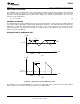
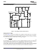
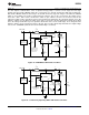
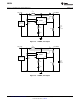
The output diode for a boost regulator must be chosen correctly depending on the output voltage and the output
current. The typical current waveform for the diode in continuous conduction mode is shown in Figure 22 (b). The
diode must be rated for a reverse voltage equal to or greater than the output voltage used. The average current
rating must be greater than the maximum load current expected, and the peak current rating must be greater
than the peak inductor current. During short circuit testing, or if short circuit conditions are possible in the
application, the diode current rating must exceed the switch current limit. Using Schottky diodes with lower
forward voltage drop will decrease power dissipation and increase efficiency.
DC GAIN AND OPEN-LOOP GAIN
Since the control stage of the converter forms a complete feedback loop with the power components, it forms a
closed-loop system that must be stabilized to avoid positive feedback and instability. A value for open-loop DC
gain will be required, from which you can calculate, or place, poles and zeros to determine the crossover
frequency and the phase margin. A high phase margin (greater than 45°) is desired for the best stability and
transient response. For the purpose of stabilizing the LM3224, choosing a crossover point well below where the
right half plane zero is located will ensure sufficient phase margin.
To ensure a bandwidth of ½ or less of the frequency of the RHP zero, calculate the open-loop DC gain, A
DC
.
After this value is known, you can calculate the crossover visually by placing a −20dB/decade slope at each pole,
and a +20dB/decade slope for each zero. The point at which the gain plot crosses unity gain, or 0dB, is the
crossover frequency. If the crossover frequency is less than ½ the RHP zero, the phase margin should be high
enough for stability. The phase margin can also be improved by adding C
C2
as discussed later in this section.
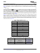
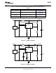
The equation for A
DC
is given below with additional equations required for the calculation:
(8)
(9)
(10)
(11)
mc ≊ 0.072fs (in V/s) (12)
where
• R
L
is the minimum load resistance
• V
IN
is the minimum input voltage
• g
m
is the error amplifier transconductance found in the Electrical Characteristics table
• R
DSON
is the value chosen from the graph "NMOS R
DSON
vs. Input Voltage" in the Typical Performance
Characteristics section (13)
Copyright © 2004–2013, Texas Instruments Incorporated Submit Documentation Feedback 13
Product Folder Links: LM3224