
Datasheet


f
S
=
V
OUT
K x R
ON
D =
t
ON
t
ON
+ t
OFF
= t
ON
x f
S
|
V
OUT
V
IN
t
ON
=
K x R
ON
V
IN
LM3151, LM3152, LM3153
www.ti.com
SNVS562G –SEPTEMBER 2008–REVISED MARCH 2011
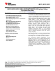
THEORY OF OPERATION
The LM3151/2/3 synchronous step-down SIMPLE SWITCHER Controller employs a Constant On-Time (COT)
architecture which is a derivative of the hysteretic control scheme. COT relies on a fixed switch on-time to
regulate the output. The on-time of the high-side switch is set internally by resistor R
ON
. The LM3151/2/3
automatically adjusts the on-time inversely with the input voltage to maintain a constant frequency. Assuming an
ideal system and V
IN
is much greater than 1V, the following approximations can be made:
The on-time, t
ON
:
where
• K = 100 pC
• R
ON
is specified in the electrical characteristics table
Control is based on a comparator and the on-timer, with the output voltage feedback (FB) attenuated and then
compared with an internal reference of 0.6V. If the attenuated FB level is below the reference, the high-side
switch is turned on for a fixed time, t
ON
, which is determined by the input voltage and the internal resistor, R
ON
.
Following this on-time, the switch remains off for a minimum off-time, t
OFF
, as specified in the Electrical
Characteristics table or until the attenuated FB voltage is less than 0.6V. This switching cycle will continue while
maintaining regulation. During continuous conduction mode (CCM), the switching frequency depends only on
duty cycle and on-time. The duty cycle can be calculated as:
Where the switching frequency of a COT regulator is:
Typical COT hysteretic controllers need a significant amount of output capacitor ESR to maintain a minimum
amount of ripple at the FB pin in order to switch properly and maintain efficient regulation. The LM3151/2/3
however utilizes proprietary, Emulated Ripple Mode Control Scheme (ERM) that allows the use of ceramic output
capacitors without additional equivalent series resistance (ESR) compensation. Not only does this reduce the
need for output capacitor ESR, but also significantly reduces the amount of output voltage ripple seen in a typical
hysteretic control scheme. The output ripple voltage can become so low that it is comparable to voltage-mode
and current-mode control schemes.
Regulation Comparator
The output voltage is sampled through the FB pin and then divided down by two internal resistors and compared
to the internal reference voltage of 0.6V by the error comparator. In normal operation, an on-time period is
initiated when the sampled output voltage at the input of the error comparator falls below 0.6V. The high-side
switch stays on for the specified on-time, causing the sampled voltage on the error comparator input to rise
above 0.6V. After the on-time period, the high-side switch stays off for the greater of the following:
1. Minimum off time as specified in the electrical characteristics table
2. The error comparator sampled voltage falls below 0.6V
Over-Voltage Comparator
The over-voltage comparator is provided to protect the output from over-voltage conditions due to sudden input
line voltage changes or output loading changes. The over-voltage comparator continuously monitors the
attenuated FB voltage versus a 0.72V internal reference. If the voltage at FB rises above 0.72V the on-time pulse
is immediately terminated. This condition can occur if the input or the output load changes suddenly. Once the
over-voltage protection is activated, the HG and LG signals remain off until the attenuated FB voltage falls below
0.72V.
Copyright © 2008–2011, Texas Instruments Incorporated Submit Documentation Feedback 9
Product Folder Links: LM3151 LM3152 LM3153