
Datasheet


LM3151, LM3152, LM3153
www.ti.com
SNVS562G –SEPTEMBER 2008–REVISED MARCH 2011
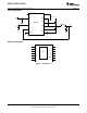
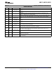
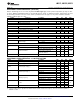
PIN DESCRIPTIONS
Pin Name Description Function
Supply Voltage for Nominally regulated to 5.95V. Connect a 1 µF to 2.2 µF decoupling capacitor from this pin to
1 VCC
FET Drivers ground.
Supply pin to the device. Nominal input range is 6V to 42V. See ordering information for Vin
2 VIN Input Supply Voltage
limitations.
To enable the IC apply a logic high signal to this pin greater than 1.26V typical or leave
3 EN Enable
floating. To disable the part, ground the EN pin.
Internally connected to the resistor divider network which sets the fixed output voltage. This
4 FB Feedback
pin also senses the output voltage faults such a over-voltage and short circuit conditions.
Ground for all internal bias and reference circuitry. Should be connected to PGND at a single
5,9 SGND Signal Ground
point.
An internal 7.7 µA current source charges an external capacitor to provide the soft-start
6 SS Soft-Start
function.
Internally not electrically connected. These pins may be left unconnected or connected to
7,8 N/C Not Connected
ground.
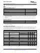
Switch pin of controller and high-gate driver lower supply rail. A boost capacitor is also
10 SW Switch Node
connected between this pin and BST pin
Gate drive signal to the high-side NMOS switch. The high-side gate driver voltage is supplied
11 HG High-Side Gate Drive
by the differential voltage between the BST pin and SW pin.
High-gate driver upper supply rail. Connect a 0.33 µF-0.47 µF capacitor from SW pin to this
Connection for
12 BST pin. An internal diode charges the capacitor during the high-side switch off-time. Do not
Bootstrap Capacitor
connect to an external supply rail.
Gate drive signal to the low-side NMOS switch. The low-side gate driver voltage is supplied by
13 LG Low-Side Gate Drive
VCC.
Synchronous rectifier MOSFET source connection. Tie to power ground plane. Should be tied
14 PGND Power Ground
to SGND at a single point.
Exposed die attach pad should be connected directly to SGND. Also used to help dissipate
EP EP Exposed Pad
heat out of the IC.
Copyright © 2008–2011, Texas Instruments Incorporated Submit Documentation Feedback 3
Product Folder Links: LM3151 LM3152 LM3153