
Datasheet


LM3151, LM3152, LM3153
SNVS562G –SEPTEMBER 2008–REVISED MARCH 2011
www.ti.com
When the FET is mounted onto the PCB, the PCB will have some additional thermal resistance such that the
total system thermal resistance of the FET package and the PCB, θ
JA
, is typically in the range of 30°C/W for this
type of FET package. The max power dissipation, Pdmax, with the FET mounted onto a PCB with a 125°C
junction temperature rise above ambient temperature and θ
JA
= 30°C/W, can be estimated by:
Pdmax = 125°C / 30°C/W = 4.1W
The system calculated Pdh of 0.674W is much less than the FET Pdmax of 4.1W and therefore the
RJK0305DPB max allowable power dissipation criteria is met.
Low-Side MOSFET
Primary loss is conduction loss given by:
Pdl = Iout
2
x R
DS(ON)
x (1-D) = 122 x 0.01 x (1-0.275) = 1W
Pdl is also less than the Pdmax specified on the RJK0305DPB MOSFET datasheet.
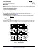
However, it is not always necessary to use the same MOSFET for both the high-side and low-side. For most
applications it is necessary to choose the high-side MOSFET with the lowest gate charge and the low-side
MOSFET is chosen for the lowest allowed R
DS(ON)
. The plateau voltage of the FET V
GS
vs Q
g
curve must be less
than VCC - 750 mV.
The current limit, I
OCL
, is calculated by estimating the R
DS(ON)
of the low-side FET at the maximum junction
temperature of 100°C. Then the following calculation of I
OCL
is:
I
OCL
= I
CL
+ ΔI
L
/ 2
I
CL
= 200 mV / 0.014 = 14.2A
I
OCL
= 14.2A + 3.6 / 2 = 16A
6. Calculate Input Capacitance
The input capacitor should be chosen so that the voltage rating is greater than the maximum input voltage which
for this example is 24V. Similar to the output capacitor, the voltage rating needed will depend on the type of
capacitor chosen. The input capacitor should also be able to handle the input rms current which is approximately
0.5 x I
OUT
. For this example the rms input current is approximately 0.5 x 12A = 6A.
The minimum capacitance with a maximum 5% input ripple ΔV
IN-MAX
= (0.05 x 12) = 0.6V:
C
IN
= [12 x 0.275 x (1-0.275)] / [500 kHz x 0.6] = 8 µF
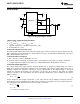
To handle the large input rms current 2 ceramic capacitors are chosen at 10 µF each with a voltage rating of 50V
and case size of 1210, that can handle 3A of rms current each. A 100 µF aluminum electrolytic is chosen to help
dampen input ringing.
C
BYP
= 0.1 µF ceramic with a voltage rating greater than maximum V
IN
7. Calculate Soft-Start Capacitor
The soft start-time should be greater than the input voltage rise time and also satisfy the following equality to
maintain a smooth transition of the output voltage to the programmed regulation voltage during startup.
t
SS
≥ (V
OUT
x C
OUT
) / (I
OCL
- I
OUT
)
5 ms > (3.3V x 300 µF) / (1.2 x 12A - 12A)
5 ms > 0.412 ms
The desired soft-start time, t
SS
, of 5 ms satisfies the equality as shown above. Therefore, the soft-start capacitor,
C
SS
, is calculated as:
C
SS
= (7.7 µA x 5 ms) / 0.6V = 0.064 µF
Let C
SS
= 0.068 µF, which is the next closest standard value. This should be a ceramic cap with a voltage rating
greater than 10V.
8. C
VCC
, C
EN
, and C
BST
C
VCC
= 1µF ceramic with a voltage rating greater than 10V
C
EN
= 1000 pF ceramic with a voltage rating greater than 10V
C
BST
= 0.47 µF ceramic with a voltage rating greater than 10V
18 Submit Documentation Feedback Copyright © 2008–2011, Texas Instruments Incorporated
Product Folder Links: LM3151 LM3152 LM3153