
Datasheet


I
CL
I
PK
'I
I
OCL
I
OUT
Inductor Current
Load Current
Increases
Normal Operation
Current Limited
'I =
(V
IN
- V
OUT
) x t
ON
L
I
valley
= I
OUT
-
'I
L
2
V
CL
(T
j
) = V
CL
x [1 + 3.3 x 10
-3
x (T
j
- 27)]
I
CL
(T
j
) =
V
CL
(T
j
)
R
DS(ON)max
LM3151, LM3152, LM3153
SNVS562G –SEPTEMBER 2008–REVISED MARCH 2011
www.ti.com
Current Limit
Current limit detection occurs during the off-time by monitoring the current through the low-side switch. If during
the off-time the current in the low-side switch exceeds the user defined current limit value, the next on-time cycle
is immediately terminated. Current sensing is achieved by comparing the voltage across the low-side switch
against an internal reference value, V
CL
, of 200 mV. If the voltage across the low-side switch exceeds 200 mV,
the current limit comparator will trigger logic to terminate the next on-time cycle. The current limit I
CL
, can be
determined as follows:
where
• I
OCL
is the user-defined average output current limit value
• R
DS(ON)max
is the resistance value of the low-side FET at the expected maximum FET junction temperature
• V
CL
is the internal current limit reference voltage
• T
j
is the junction temperature of the LM3151/2/3
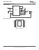
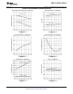
Figure 12 illustrates the inductor current waveform. During normal operation, the output current ripple is dictated
by the switching of the FETs. The current through the low-side switch, I
valley
, is sampled at the end of each
switching cycle and compared to the current limit threshold voltage, V
CL
. The valley current can be calculated as
follows:
where
• I
OUT
is the average output current
• ΔI
L
is the peak-to-peak inductor ripple current
If an overload condition occurs, the current through the low-side switch will increase which will cause the current
limit comparator to trigger the logic to skip the next on-time cycle. The IC will then try to recover by checking the
valley current during each off-time. If the valley current is greater than or equal to I
CL
, then the IC will keep the
low-side FET on and allow the inductor current to further decay.
Throughout the whole process, regardless of the load current, the on-time of the controller will stay constant and
thereby the positive ripple current slope will remain constant. During each on-time the current ramps up an
amount equal to:
The valley current limit feature prevents current runaway conditions due to propagation delays or inductor
saturation since the inductor current is forced to decay following any overload conditions.
Figure 12. Inductor Current - Current Limit Operation
10 Submit Documentation Feedback Copyright © 2008–2011, Texas Instruments Incorporated
Product Folder Links: LM3151 LM3152 LM3153