
Datasheet


Table Of Contents
ET = (Vinmax ± V
OUT
) x
Vinmax
V
OUT
x
f
S
1000
(V x Ps)
LM3150
SNVS561D –SEPTEMBER 2008–REVISED MARCH 2011
www.ti.com
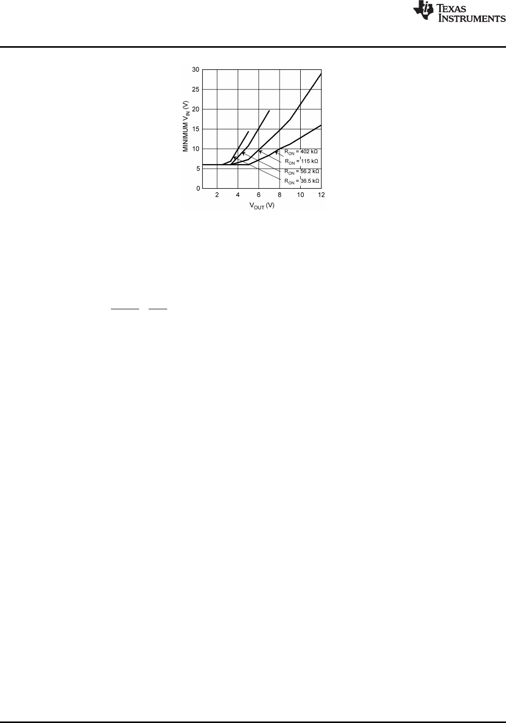
Figure 13. Minimum V
IN
vs. V
OUT
I
OUT
= 10 A
4. Determine Inductor Required Using Figure 14
To use the nomograph in Figure 14, calculate the inductor volt-microsecond constant ET from the following
formula:
where
• f
s
is in kHz units (16)
The intersection of the Load Current and the Volt-microseconds lines on the chart below will determine which
inductors are capable for use in the design. The chart shows a sample of parts that can be used. The offline
calculator tools and WEBENCH
®
will fully calculate the requirements for the components needed for the design.
12 Submit Documentation Feedback Copyright © 2008–2011, Texas Instruments Incorporated
Product Folder Links: LM3150