
Datasheet


Table Of Contents
I
CL
I
PK
'I
I
OCL
I
OUT
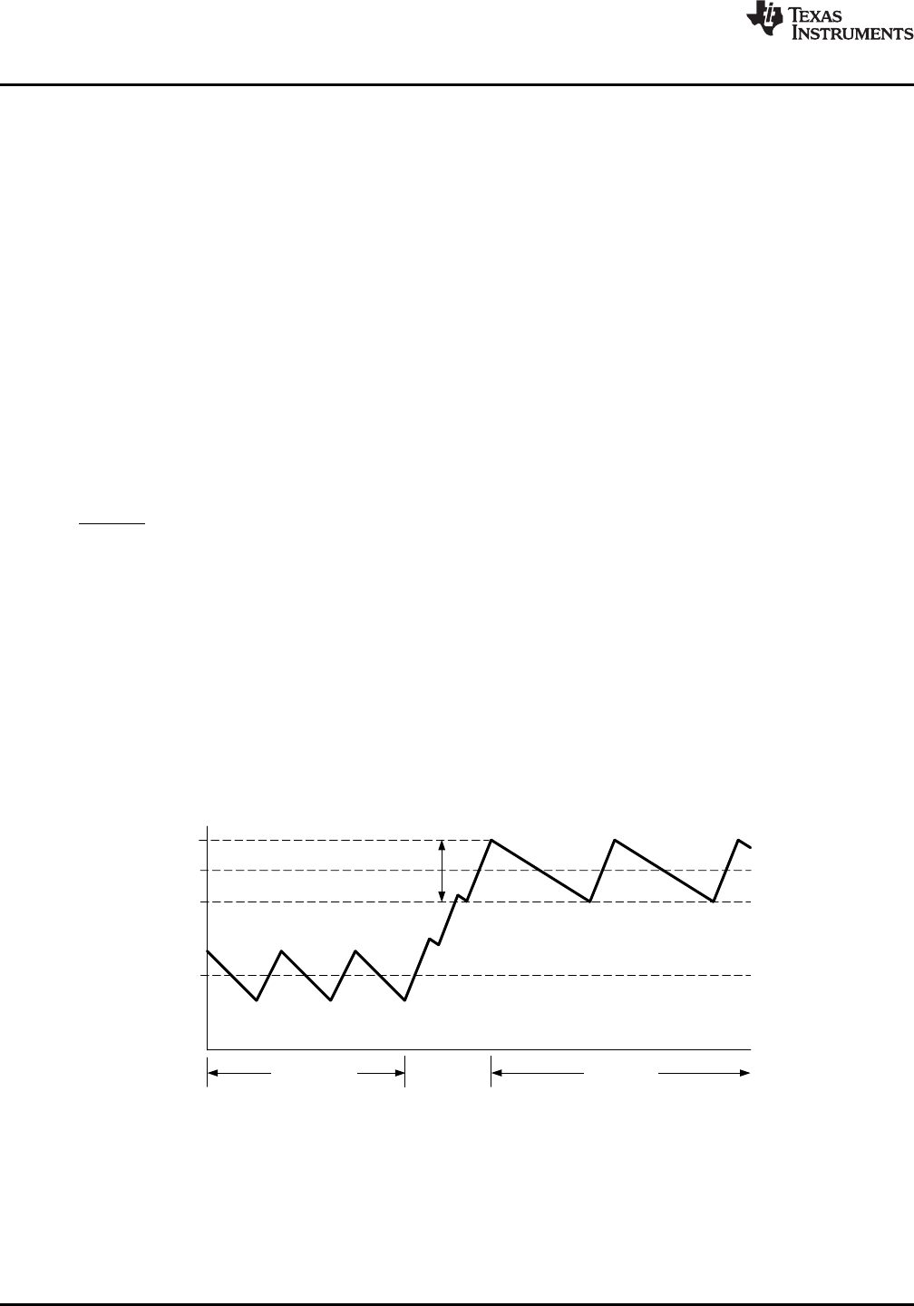
Inductor Current
Load Current
Increases
Normal Operation
Current Limited
t
SS
=
V
ref
x C
SS
I
SS
LM3150
SNVS561D –SEPTEMBER 2008–REVISED MARCH 2011
www.ti.com
I
LIM-TH
(T
J
) = I
LIM-TH
x [1 + 3.3 x 10
-3
x (T
J
- 27)] (10)
To calculate the R
LIM
value with temperature compensation, substitute equation (10) into I
LIM-TH
in equation (7).
Short-Circuit Protection
The LM3150 will sense a short-circuit on the output by monitoring the output voltage. When the feedback voltage
has fallen below 60% of the reference voltage, V
ref
x 0.6 (≈ 0.36V), short-circuit mode of operation will start.
During short-circuit operation, the SS pin is discharged and the output voltage will fall to 0V. The SS pin voltage,
V
SS
, is then ramped back up at the rate determined by the SS capacitor and I
SS
until V
SS
reaches 0.7V. During
this re-ramp phase, if the short-circuit fault is still present the output current will be equal to the set current limit.
Once the soft-start voltage reaches 0.7V the output voltage is sensed again and if the V
FB
is still below V
ref
x 0.6
then the SS pin is discharged again and the cycle repeats until the short-circuit fault is removed.
Soft-Start
The soft-start (SS) feature allows the regulator to gradually reach a steady-state operating point, which reduces
start-up stresses and current surges. At turn-on, while VCC is below the under-voltage threshold, the SS pin is
internally grounded and V
OUT
is held at 0V. The SS capacitor is used to slowly ramp V
FB
from 0V to 0.6V. By
changing the capacitor value, the duration of start-up can be changed accordingly. The start-up time can be
calculated using the following equation:
where
• t
SS
is measured in seconds
• V
ref
= 0.6V
• I
SS
is the soft-start pin source current, which is typically 7.7 µA (refer to Electrical Characteristics table) (11)
An internal switch grounds the SS pin if VCC is below the under-voltage lockout threshold, if a thermal shutdown
occurs, or if the EN pin is grounded. By using an externally controlled switch, the output voltage can be shut off
by grounding the SS pin.
During startup the LM3150 will operate in diode emulation mode, where the low-side gate LG will turn off and
remain off when the inductor current falls to zero. Diode emulation mode will allow start-up into a pre-biased
output voltage. When soft-start is greater than 0.7V, the LM3150 will remain in continuous conduction mode.
During diode emulation mode at current limit the low-gate will remain off when the inductor current is off.
Figure 12. Inductor Current - Current Limit Operation
The soft-start time should be greater than the input voltage rise time and also satisfy the following equality to
maintain a smooth transition of the output voltage to the programmed regulation voltage during startup.
t
SS
≥ (V
OUT
x C
OUT
) / (I
OCL
- I
OUT
) (12)
10 Submit Documentation Feedback Copyright © 2008–2011, Texas Instruments Incorporated
Product Folder Links: LM3150