
Datasheet


LM185-2.5-N, LM285-2.5-N, LM385-2.5-N
SNVS743D –DECEMBER 1999–REVISED MARCH 2013
www.ti.com
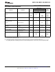
ELECTRICAL CHARACTERISTICS
LM185-2.5-N
LM385B-2.5-N
LM185BX-2.5-N
LM185BY-2.5-N LM385BX-2.5-N
LM385-2.5-N
LM285-2.5-N Units
Parameter Conditions Typ
(Limit)
LM285BX-2.5-N LM385BY-2.5-N
LM285BY-2.5-N
Tested Limit
(1)(2)
Design Tested Design Tested Design
Limit
(3)
Limit
(1)
Limit
(3)
Limit
(1)
Limit
(3)
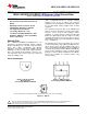
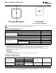
Reverse Breakdown T
A
= 25°C, 2.5 2.462 2.462 2.425 V(Min)
Voltage 20 μA ≤ I
R
≤ 20 mA 2.538 2.538 2.575 V(Max)
Minimum Operating 13 20 30 20 30 20 30 μA
Current (Max)
LM385M3-2.5-N 15 20
Reverse Breakdown 20 μA ≤ I
R
≤ 1 mA 1 1.5 2.0 2.5 2.0 2.5 mV
Voltage Change (Max)
with Current
1 mA ≤ I
R
≤ 20 mA 10 20 20 25 20 25 mV
(Max)
Reverse Dynamic I
R
= 100 μA, 1 Ω
Impedance f = 20 Hz
Wideband Noise I
R
= 100 μA,
120 μV
(rms)
10 Hz ≤ f ≤ 10 kHz
Long Term Stability I
R
= 100 μA,
T = 1000 Hr, 20 ppm
T
A
= 25°C ±0.1°C
Average I
R
= 100 μA
Temperature
X Suffix 30 30 ppm/°C
Coefficient
(4)
Y Suffix 50 50 ppm/°C
All Others 150 150 150 ppm/°C
(Max)
(1) Specified and 100% production tested.
(2) A military RETS electrical specification available on request.
(3) Specified, but not 100% production tested. These limits are not used to calculate average outgoing quality levels.
(4) The average temperature coefficient is defined as the maximum deviation of reference voltage at all measured temperatures between
the operating T
MAX
and T
MIN
, divided by T
MAX
–T
MIN
. The measured temperatures are −55°C, −40°C, 0°C, 25°C, 70°C, 85°C, 125°C.
4 Submit Documentation Feedback Copyright © 1999–2013, Texas Instruments Incorporated
Product Folder Links: LM185-2.5-N LM285-2.5-N LM385-2.5-N