
Datasheet


LM185-1.2-N, LM285-1.2-N, LM385-1.2-N
www.ti.com
SNVS742E –JANUARY 2000–REVISED APRIL 2013
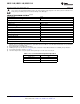
ELECTRICAL CHARACTERISTICS
(1)
LM185-1.2-N
LM185BX-1.2-N LM385B-1.2-N
LM185BY-1.2-N LM385BX-1.2-N
LM385-1.2-N
LM285-1.2-N LM385BY-1.2-N
Units
Parameter Conditions Typ
LM285BX-1.2-N
(Limit)
LM285BY-1.2-N
Tested Design Tested Design Tested Design
Limit
(2)
Limit
(4)
Limit
(2)
Limit
(4)
Limit
(2)
Limit
(4)
(3)
Reverse Breakdown T
A
= 25°C, 1.23 1.223 1.223 1.205 V(Min)
5
Voltage 10μA ≤ I
R
≤ 20mA 1.247 1.247 1.260 V(Max)
Minimum Operating 8 10 20 15 20 15 20 μA
Current
LM385M3-1.2-N 10 15 (Max)
Reverse Breakdown 10μA ≤ I
R
≤ 1mA 1 1.5 1 1.5 1 1.5 mV
Voltage Change with
(Max)
Current
1mA ≤ I
R
≤ 20mA 10 20 20 25 20 25 mV
(Max)
Reverse Dynamic I
R
= 100μA, f = 20Hz 1 Ω
Impedance
Wideband Noise I
R
= 100μA, 60 μV
(rms) 10Hz ≤ f ≤ 10kHz
Long Term Stability I
R
= 100μA, T = 1000 Hr, 20 ppm
T
A
= 25°C ±0.1°C
Average Temperature I
R
= 100μA
Coefficient
(5)
X Suffix 30 30 ppm/°C
Y Suffix 50 50 ppm/°C
All Others 150 150 150 ppm/°C
(Max)
(1) Parameters identified with boldface type apply at temperature extremes. All other numbers apply at T
A
= T
J
= 25°C.
(2) Production tested.
(3) A military RETS electrical specification is available on request.
(4) Specified by design. Not production tested. These limits are not used to calculate average outgoing quality levels.
(5) The average temperature coefficient is defined as the maximum deviation of reference voltage at all measured temperatures between
the operating T
MAX
and T
MIN
, divided by T
MAX
− T
MIN
. The measured temperatures are −55°C, −40°C, 0°C, 25°C, 70°C, 85°C, 125°C.
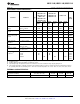
THERMAL CHARACTERISTICS
Thermal Resistance TO-92 TO SOIC SOT-23
180°C/W (0.4″ leads)
θ
JA
(junction to ambient) 440°C/W 165°C/W 283°C/W
170°C/W (0.125″ leads)
θ
JC
(junction to case) N/A 80°C/W N/A N/A
Copyright © 2000–2013, Texas Instruments Incorporated Submit Documentation Feedback 3
Product Folder Links: LM185-1.2-N LM285-1.2-N LM385-1.2-N