
Datasheet


Table Of Contents
- LM2853
- General Description
- Features
- Applications
- Typical Application Circuit
- Connection Diagram
- Ordering Information
- Pin Descriptions
- Absolute Maximum Ratings
- Operating Ratings
- Electrical Characteristics
- Typical Performance Characteristics
- Block Diagram
- Applications Information
- LM2853 Example Circuit Schematic
- Physical Dimensions
Absolute Maximum Ratings (Note 1)
If Military/Aerospace specified devices are required,
please contact the National Semiconductor Sales Office/
Distributors for availability and specifications.
AVIN, PVIN, EN, SNS, SW, SS −0.3V to 6.0V
ESD Susceptibility (Note 2) 2kV
Power Dissipation Internally Limited
Storage Temperature Range −65˚C to +150˚C
Maximum Junction Temp. 150˚C
14-Pin Exposed Pad TSSOP Package
Infrared (15 sec) 220˚C
Vapor Phase (60 sec) 215˚C
Soldering (10 sec) 260˚C
Operating Ratings (Note 1)
PVIN to GND 1.5V to 5.5V
AVIN to GND 3.0V to 5.5V
Junction Temperature −40˚C to +125˚C
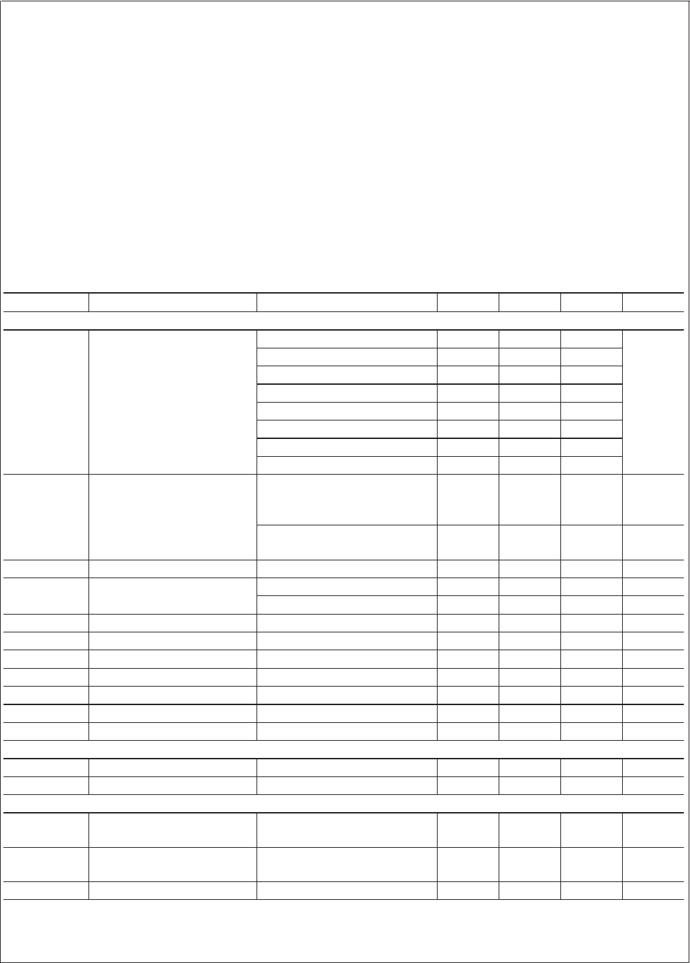
Electrical Characteristics Specifications with standard typeface are for T
J
= 25˚C, and those in bold face
type apply over the full Junction Temperature Range (−40˚C to 125˚C). Minimum and Maximum limits are guaranteed through
test, design or statistical correlation. Typical values represent the most likely parametric norm at T
J
= 25˚C and are provided
for reference purposes only. Unless otherwise specified AVIN = PVIN = 5V.
Symbol Parameter Conditions Min Typ Max Units
SYSTEM PARAMETERS
V
OUT
Voltage Tolerance (Note 3) V
OUT
= 0.8V option 0.782 0.8 0.818
V
V
OUT
= 1.0V option 0.9775 1.0 1.0225
V
OUT
= 1.2V option 1.1730 1.2 1.227
V
OUT
= 1.5V option 1.4663 1.5 1.5337
V
OUT
= 1.8V option 1.7595 1.8 1.8405
V
OUT
= 2.5V option 2.4437 2.5 2.5563
V
OUT
= 3.0V option 2.9325 3.0 3.0675
V
OUT
= 3.3V option 3.2257 3.3 3.3743
∆V
OUT
/∆AVIN Line Regulation (Note 3) V
OUT
= 0.8V, 1.0V, 1.2V, 1.5V,
1.8V or 2.5V
3.0V ≤ AVIN ≤ 5.5V
0.2 1.1 %
V
OUT
= 3.0V or 3.3V
3.5V ≤ AVIN ≤ 5.5V
0.2 1.1 %
∆V
OUT
/∆I
O
Load Regulation Normal operation 2 mV/A
V
ON
UVLO Threshold (AVIN) Rising 2.47 3.0 V
Falling Hysteresis 50 155 260 mV
R
DS(ON)-P
PFET On Resistance Isw = 3A 40 120 mΩ
R
DS(ON)-N
NFET On Resistance Isw = 3A 32 100 mΩ
R
SS
Soft-Start Resistance 450 kΩ
I
CL
Peak Current Limit Threshold 3.6 5A
I
Q
Operating Current Non-switching 0.85 2 mA
I
SD
Shutdown Quiescent Current EN = 0V 12 50 µA
R
SNS
Sense Pin Resistance 432 kΩ
PWM
f
osc
Switching Frequency . 325 550 725 kHz
D
range
Duty Cycle Range 0 100 %
ENABLE CONTROL (Note 4)
V
IH
EN Pin Minimum High Input 75 %of
AVIN
V
IL
EN Pin Maximum Low Input 25 %of
AVIN
I
EN
EN Pin Pullup Current EN = 0V 1.5 µA
LM2853
www.national.com3