
Datasheet


Table Of Contents
- Features
- Applications
- Description
- Absolute Maximum Ratings
- Operating Ratings
- Electrical Characteristics
- Typical Performance Characteristics
- Block Diagram
- Application Information
- Revision History
G
EA-ACTUAL
x OPG
H
EA
=
1 + G
EA-ACTUAL
+ OPG
Z
1
=
R
C2
+
1
sC
C3
R
C1
+ R
C2
1
sC
C3
+
R
C1
1
Z
F
=
sC
C1
x
10,000 +
1
sC
C2
10,000 +
1
sC
C1
1
sC
C2
+
G
EA-ACTUAL
=
Z
F
Z
I
1
R
C2
=
2SxC
C3
x
f
P1
= 2.55 k:
1
R
C1
=
2SxC
C2
x
f
Z1
= 39.8 k:
1
C
C3
=
2S x 10,000
x
= 2.73 nF
1
f
Z2
-
1
f
P1
1
C
C2
=
A
EA
x 10,000
- C
C1
= 882 pF
LM2743
www.ti.com
SNVS276G –APRIL 2004–REVISED MARCH 2013
In practice, a good trade off between phase margin and bandwidth can be obtained by selecting the closest
±10% capacitor values above what are suggested for C
C1
and C
C2
, the closest ±10% capacitor value below the
suggestion for C
C3
, and the closest ±1% resistor values below the suggestions for R
C1
, R
C2
. Note that if the
suggested value for R
C2
is less than 100Ω, it should be replaced by a short circuit. Following this guideline, the
compensation components will be:
C
C1
= 27pF ±10%
C
C2
= 820pF ±10%
C
C3
= 2.7nF ±10%
R
C1
= 39.2kΩ ±1%
R
C2
= 2.55kΩ ±1%
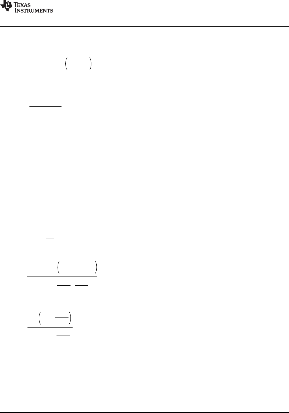
The transfer function of the compensation block can be derived by considering the compensation components as
impedance blocks Z
F
and Z
I
around an inverting op-amp:
As with the generic equation, G
EA-ACTUAL
must be modified to take into account the limited bandwidth of the error
amplifier. The result is:
The total control loop transfer function H is equal to the power stage transfer function multiplied by the error
amplifier transfer function.
H = G
PS
x H
EA
Copyright © 2004–2013, Texas Instruments Incorporated Submit Documentation Feedback 25
Product Folder Links: LM2743