
Datasheet


Table Of Contents
LM2642
SNVS203I –MAY 2002–REVISED APRIL 2013
www.ti.com
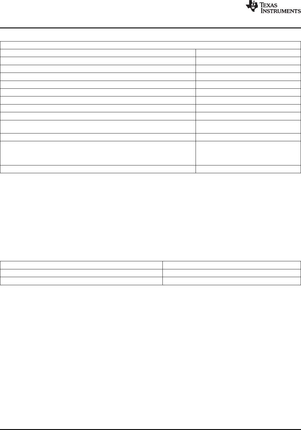
ABSOLUTE MAXIMUM RATINGS
(1)
Voltages from the indicated pins to SGND/PGND:
VIN, ILIM1, ILIM2, KS1, KS2 −0.3V to 32V
SW1, SW2, RSNS1, RSNS2 −0.3 to (V
IN
+ 0.3)V
FB1, FB2, VDD1, VDD2 −0.3V to 6V
PGOOD, COMP1, COMP2, UV Delay −0.3V to (VLIN5 +0.3)V
ON/SS1, ON/SS2
(2)
−0.3V to (VLIN5 +0.6)V
CBOOT1 to SW1, CBOOT2 to SW2 −0.3V to 7V
LDRV1, LDRV2 −0.3V to (VDD+0.3)V
HDRV1 to SW1, HDRV2 to SW2 −0.3V
HDRV1 to CBOOT1, HDRV2 to CBOOT2 +0.3V
Power Dissipation (T
A
= 25°C),
(3)
1.1W
Ambient Storage Temperature Range −65°C to +150°C
Soldering Dwell Time, Temperature
(4)
Wave 4 sec, 260°C
Infrared 10sec, 240°C
Vapor Phase 75sec, 219°C
ESD Rating
(5)
2kV
(1) Absolute maximum ratings indicate limits beyond which damage to the device may occur. Operating Range indicates conditions for
which the device is intended to be functional, but does not ensure specific performance limits. For ensured specifications and test
conditions, see the Electrical Characteristics. The specifications apply only for the test conditions. Some performance characteristics
may degrade when the device is not operated under the listed test conditions.
(2) ON/SS1 and ON/SS2 are internally pulled up to one diode drop above VLIN5. Do not apply an external pull-up voltage to these pins. It
may cause damage to the IC.
(3) The maximum allowable power dissipation is calculated by using P
DMAX
= (T
JMAX
- T
A
)/θ
JA
, where T
JMAX
is the maximum junction
temperature, T
A
is the ambient temperature and θ
JA
is the junction-to-ambient thermal resistance of the specified package. The 1.1W
rating results from using 125°C, 25°C, and 90.6°C/W for T
JMAX
, T
A
, and θ
JA
respectively. A θ
JA
of 90.6°C/W represents the worst-case
condition of no heat sinking of the 28-pin TSSOP. A thermal shutdown will occur if the temperature exceeds the maximum junction
temperature of the device.
(4) For detailed information on soldering plastic small-outline packages, see the TI website at www.ti.com/packaging.
(5) For testing purposes, ESD was applied using the human-body model, a 100pF capacitor discharged through a 1.5kΩ resistor.
OPERATING RATINGS
(1)
VIN (VLIN5 tied to VIN) 4.5V to 5.5V
VIN (VIN and VLIN5 separate) 5.5V to 30V
Junction Temperature −40°C to +125°C
(1) Absolute maximum ratings indicate limits beyond which damage to the device may occur. Operating Range indicates conditions for
which the device is intended to be functional, but does not ensure specific performance limits. For ensured specifications and test
conditions, see the Electrical Characteristics. The specifications apply only for the test conditions. Some performance characteristics
may degrade when the device is not operated under the listed test conditions.
4 Submit Documentation Feedback Copyright © 2002–2013, Texas Instruments Incorporated
Product Folder Links: LM2642