
Datasheet


Table Of Contents
V
o
V
c
R
2
R
1
g
m
compensation
network
C
C1
C
C2
R
C1
R
C2
LM2642
SNVS203I –MAY 2002–REVISED APRIL 2013
www.ti.com
The value of C
c1
should be within the range determined by Fpmin/max. A higher value will generally provide a
more stable loop, but too high a value will slow the transient response time.
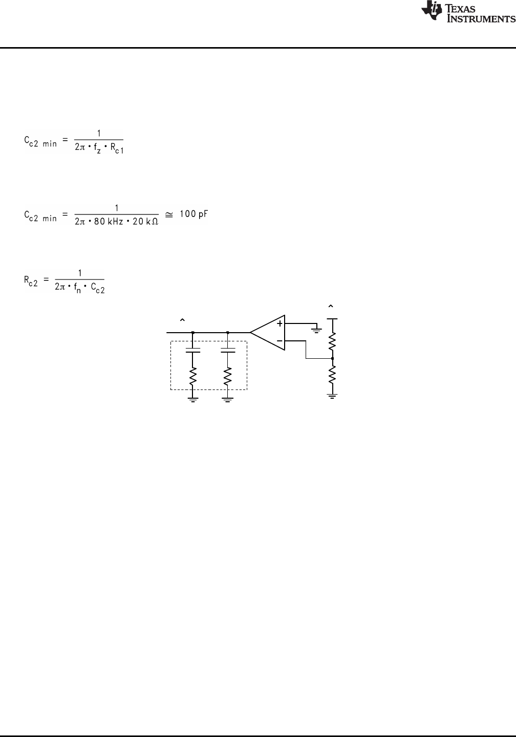
The compensation network (Figure 31) will also introduce a low frequency pole which will be close to 0Hz.
A second pole should also be placed at fz. This pole can be created with a single capacitor Cc2 and a shorted
Rc2 (see Figure 31). The minimum value for this capacitor can be calculated by:
(32)
Cc2 may not be necessary, however it does create a more stable control loop. This is especially important with
high load currents and in current sharing mode.
Example: fz = 80 kHz, Rc1 = 20 KΩ:
(33)
A second zero can also be added with a resistor in series with Cc2. If used, this zero should be placed at fn,
where the control to output gain rolls off at -40dB/dec. Generally, fn will be well below the 0dB level and thus will
have little effect on stability. Rc2 can be calculated with the following equation:
(34)
Figure 31. Compensation Network
24 Submit Documentation Feedback Copyright © 2002–2013, Texas Instruments Incorporated
Product Folder Links: LM2642