
Datasheet


Table Of Contents
fp max =
2S 300k 8P 100PF
x
x
x
.5
1
2S 1.7: 100PF
x
x
+
= 1.27kHz
-20dB/dec
(f
p1
is at zero frequency)
-20
dB
/
dec
FREQUENCY
GAIN (dB)
B
f
z1
f
z2
f
p2
LM2642
www.ti.com
SNVS203I –MAY 2002–REVISED APRIL 2013
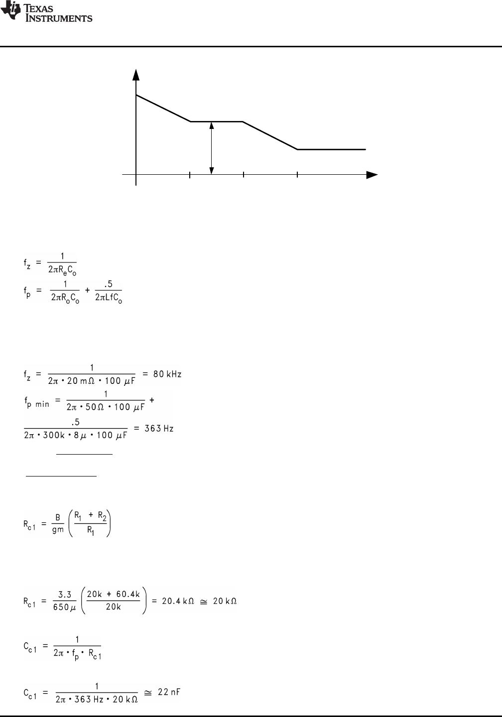
Figure 30. Output-Control Transfer Function
The control-output corner frequencies, and thus the desired compensation corner frequencies, can be
determined approximately by the following equations:
(23)
(24)
Since fp is determined by the output network, it will shift with loading (Ro) and duty cycle. First determine the
range of frequencies (fpmin/max) of the pole across the expected load range, then place the first compensation
zero within that range.
Example: R
e
= 20mΩ, C
o
= 100µF, R
omax
= 5V/100mA = 50Ω, R
omin
= 5V/3A = 1.7Ω:
(25)
(26)
(27)
Once the fp range is determined, R
c1
should be calculated using:
(28)
Where B is the desired gain in V/V at fp (fz1), gm is the transconductance of the error amplifier, and R1 and R2
are the feedback resistors. A gain value around 10dB (3.3v/v) is generally a good starting point.
Example: B = 3.3 v/v, gm=650 m, R1 = 20 KΩ, R2 = 60.4 KΩ:
(29)
Bandwidth will vary proportional to the value of Rc1. Next, Cc1 can be determined with the following equation:
(30)
Example: fpmin = 363 Hz, Rc1=20 KΩ:
(31)
Copyright © 2002–2013, Texas Instruments Incorporated Submit Documentation Feedback 23
Product Folder Links: LM2642