
Datasheet


Table Of Contents
10 100
1
k
10
k
100
k
1M
FREQUENCY
(Hz)
-60
-40
-20
0
20
GAIN
(dB)
0
-45
-90
-135
-180
PHASE
(
°
)
Asymptoti
c
Gain
Phas
e
LM2642
SNVS203I –MAY 2002–REVISED APRIL 2013
www.ti.com
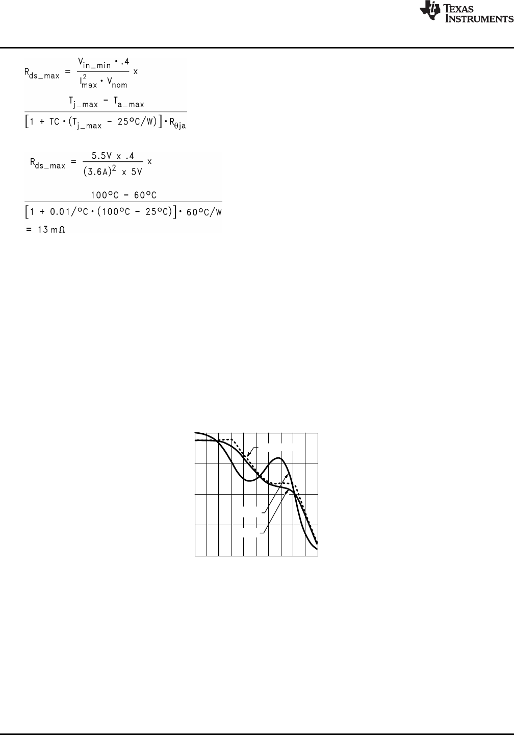
(21)
Example: Tj_max = 100°C, Ta_max = 60°C, Rqja = 60°C/W, Vin_min = 5.5V, Vnom = 5V, and Iload_max = 3.6A.
(22)
When using FETs in parallel, the same guidelines apply to the top FET as apply to the bottom FET.
LOOP COMPENSATION
The general purpose of loop compensation is to meet static and dynamic performance requirements while
maintaining stability. Loop gain is what is usually checked to determine small-signal performance. Loop gain is
equal to the product of control-output transfer function and the output-control transfer function (the compensation
network transfer function). Generally speaking it is a good idea to have a loop gain slope that is -20dB /decade
from a very low frequency to well beyond the crossover frequency. The crossover frequency should not exceed
one-fifth of the switching frequency, i.e. 60kHz in the case of LM2642. The higher the bandwidth is, the faster the
load transient response speed will potentially be. However, if the duty cycle saturates during a load transient,
further increasing the small signal bandwidth will not help. Since the control-output transfer function usually has
very limited low frequency gain, it is a good idea to place a pole in the compensation at zero frequency, so that
the low frequency gain will be relatively large. A large DC gain means high DC regulation accuracy (i.e. DC
voltage changes little with load or line variations). The rest of the compensation scheme depends highly on the
shape of the control-output plot.
Figure 29. Control-Output Transfer Function
As shown in Figure 29, the control-output transfer function consists of one pole (fp), one zero (fz), and a double
pole at fn (half the switching frequency). The following can be done to create a -20dB /decade roll-off of the loop
gain: Place the first pole at 0Hz, the first zero at fp, the second pole at fz, and the second zero at fn. The
resulting output-control transfer function is shown in Figure 30.
22 Submit Documentation Feedback Copyright © 2002–2013, Texas Instruments Incorporated
Product Folder Links: LM2642