
Datasheet


Table Of Contents
LM2642
SNVS203I –MAY 2002–REVISED APRIL 2013
www.ti.com
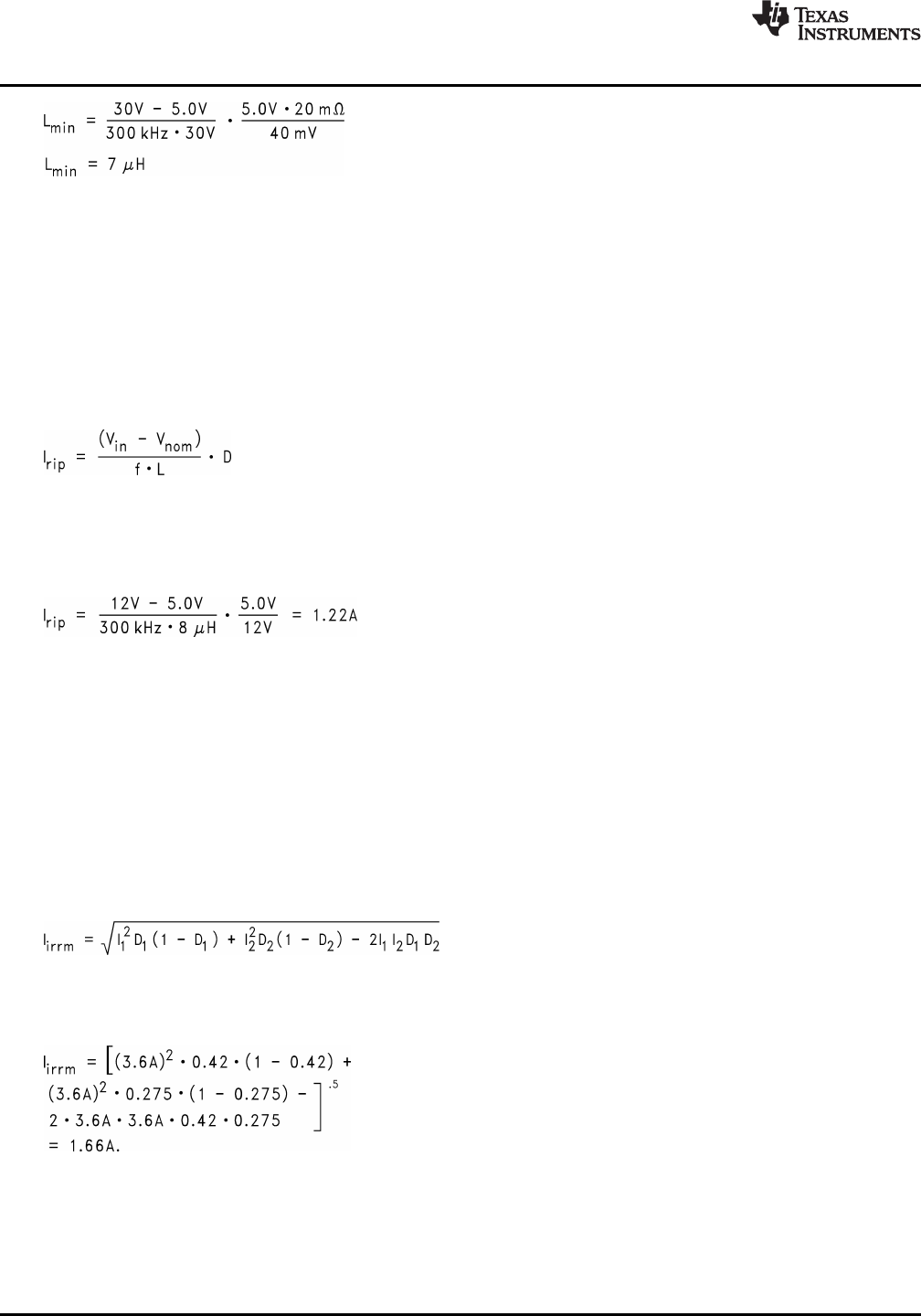
(13)
Lmin = 7µH
The actual selection process usually involves several iterations of all of the above steps, from ripple voltage
selection, to capacitor selection, to inductance calculations. Both the highest and the lowest input and output
voltages and load transient requirements should be considered. If an inductance value larger than Lmin is
selected, make sure that the Cmin requirement is not violated.
Priority should be given to parameters that are not flexible or more costly. For example, if there are very few
types of capacitors to choose from, it may be a good idea to adjust the inductance value so that a requirement of
3.2 capacitors can be reduced to 3 capacitors.
Since inductor ripple current is often the criterion for selecting an output inductor, it is a good idea to double-
check this value. The equation is:
(14)
Where D is the duty cycle, defined by V
nom
/V
in
.
Also important is the ripple content, which is defined by Irip /Inom. Generally speaking, a ripple content of less
than 50% is ok. Larger ripple content will cause too much loss in the inductor.
Example: Vin = 12V, Vnom = 5.0V, f = 300kHz, L = 8µH
(15)
Given a maximum load current of 3A, the ripple content is 1.2A / 3A = 40%.
When choosing the inductor, the saturation current should be higher than the maximum peak inductor current
and the RMS current rating should be higher than the maximum load current.
INPUT CAPACITOR SELECTION
The fact that the two switching channels of the LM2642 are 180° out of phase will reduce the RMS value of the
ripple current seen by the input capacitors. This will help extend input capacitor life span and result in a more
efficient system. Input capacitors must be selected that can handle both the maximum ripple RMS current at
highest ambient temperature as well as the maximum input voltage. In applications in which output voltages are
less than half of the input voltage, the corresponding duty cycles will be less than 50%. This means there will be
no overlap between the two channels' input current pulses. The equation for calculating the maximum total input
ripple RMS current for duty cycles under 50% is:
(16)
where I1 is maximum load current of Channel 1, I2 is the maximum load current of Channel 2, D1 is the duty
cycle of Channel 1, and D2 is the duty cycle of Channel 2.
Example: Imax_1 = 3.6A, Imax_2 = 3.6A, D1 = 0.42, and D2 = 0.275
(17)
Choose input capacitors that can handle 1.66A ripple RMS current at highest ambient temperature. In
applications where output voltages are greater than half the input voltage, the corresponding duty cycles will be
greater than 50%, and there will be overlapping input current pulses. Input ripple current will be highest under
these circumstances. The input RMS current in this case is given by:
20 Submit Documentation Feedback Copyright © 2002–2013, Texas Instruments Incorporated
Product Folder Links: LM2642