
Datasheet


Table Of Contents
+
-
+
-
10uA
comp
ISENSE
amp
POWER
SUPPLY
100
100
100pF
100pF
LIMx
KSx
RSNSx
10nF
20m
13k
LIMx
Rsw
CBOOTx
4R7
HDRVx
SWx
0.1uF
LM2642
SNVS203I –MAY 2002–REVISED APRIL 2013
www.ti.com
Figure 25. SW Series Resistor
CURRENT SENSING AND LIMITING
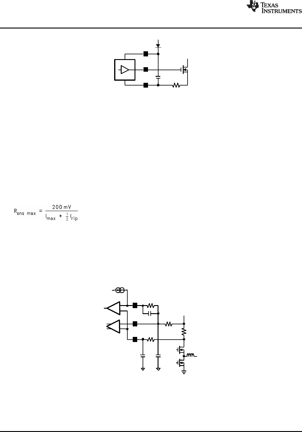
As shown in Figure 26, the KSx and RSNSx pins are the inputs of the current sense amplifier. Current sensing is
accomplished either by sensing the Vds of the top FET or by sensing the voltage across a current sense resistor
connected from VIN to the drain of the top FET. The advantage of sensing current across the top FET are
reduced parts count, cost and power loss, whereas using a current sense resistor improves the current sense
accuracy. Keeping the differential current-sense voltage below 200mV ensures linear operation of the current
sense amplifier. Therefore, the Rdson of the top FET or the current sense resistor must be small enough so that
the current sense voltage does not exceed 200mV when the top FET is on. There is a leading edge blanking
circuit that forces the top FET on for at least 166ns. Beyond this minimum on time, the output of the PWM
comparator is used to turn off the top FET. Additionally, a minimum voltage of at least 50mV across Rsns is
recommended to ensure a high SNR at the current sense amplifier.
Assuming a maximum of 200mV across Rsns, the current sense resistor can be calculated as follows:
(1)
where Imax is the maximum expected load current, including overload multiplier (ie:120%), and Irip is the
inductor ripple current (See equation 7). The above equation gives the maximum allowable value for Rsns.
Switching losses will increase with Rsns, thus lowering efficiency.
The peak current limit is set by an external resistor connected between the ILIMx pin and the KSx pin. An
internal 10µA current sink on the ILIMx pin produces a voltage across the resistor to set the current limit
threshold which is compared to the current sense voltage. A 10nF capacitor across this resistor is required to
filter unwanted noise that could improperly trip the current limit comparator.
Figure 26. Current Sense and Current Limit
Current limit is activated when the inductor current is high enough to cause the voltage at the RSNSx pin to be
lower than that of the ILIMx pin. This toggles the comparator, thus turning off the top FET immediately. The
comparator is disabled either when the top FET is turned off or during the leading edge blanking time. The
equation for current limit resistor, R
lim
, is as follows:
16 Submit Documentation Feedback Copyright © 2002–2013, Texas Instruments Incorporated
Product Folder Links: LM2642