
Datasheet


Table Of Contents
+
-
+
-
SS:0.55V
OP:2V
0.45V
high clamp
low clamp
COMPx
+
-
2uA
7uA
+
-
Q
Q
R
S
S>R
1.2V/
1.05V
ON/OFF
comparator
+
-
S/S level
S/S buffer
ON: 2uA source
Fault: 5uA sink
ON/SSx
ONx
fault
disable
LM2642
www.ti.com
SNVS203I –MAY 2002–REVISED APRIL 2013
APPLICATION INFORMATION
OPERATION DESCRIPTIONS
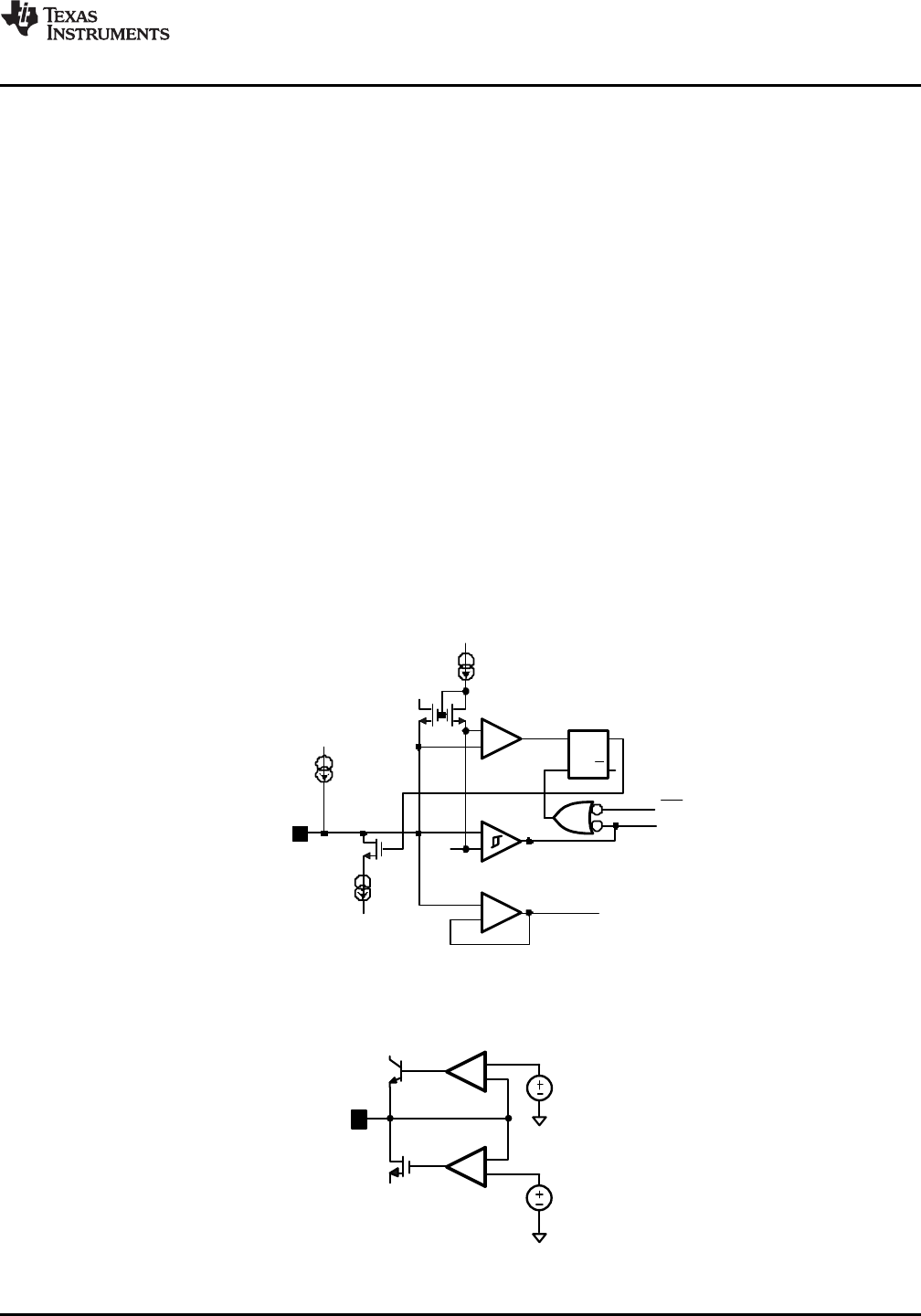
SOFT START
The ON/SS1 pin has dual functionality as both channel enable and soft start control. The soft start block diagram
is shown in Figure 22.
The LM2642 will remain in shutdown mode while both soft start pins are grounded.In a normal application (with a
soft start capacitor connected between the ON/SS1 pin and SGND) soft start functions as follows. As the input
voltage rises (note: Iss starts to flow when VIN ≥ 2.2V), the internal 5V LDO starts up, and an internal 2µA
current charges the soft start capacitor. During soft start phase, the error amplifier output voltage at the COMPx
pin is clamped at 0.55V and the duty cycle is controlled only by the soft start voltage. As the SSx pin voltage
ramps up, the duty cycle increases proportional to the soft start ramp, causing the output voltage to ramp up. The
rate at which the duty cycle increases depends on the capacitance of the soft start capacitor. The higher the
capacitance, the slower the output voltage ramps up. When the corresponding output voltage exceeds 98%
(typical) of the set target voltage, the regulator switches from soft start to normal operating mode. At this time,
the 0.55V clamp at the output of the error amplifier releases and peak current feedback control takes over. Once
in peak current feedback control mode, the output of the error amplifier will travel within the 0.5V and 2V window
to achieve PWM control. See Figure 23.
During soft start, over-voltage protection and current limit remain in effect. The under voltage protection feature is
activated when the ON/SS pin exceeds the timeout threshold (3.3V typical). If the ON/SSx capacitor is too small,
the duty cycle may increase too rapidly, causing the device to latch off due to output voltage overshoot above the
OVP threshold. This becomes more likely in applications requiring low output voltage, high input voltage and light
load. A capacitance of 10nF is recommended at each soft start pin to provide a smooth monotonic output ramp.
Figure 22. Soft Start and ON/OFF
Figure 23. Voltage Clamp at COMPx Pin
Copyright © 2002–2013, Texas Instruments Incorporated Submit Documentation Feedback 13
Product Folder Links: LM2642