
Datasheet


Table Of Contents
- Features
- Applications
- Description
- Absolute Maximum Ratings
- Operating Conditions
- LM2596-3.3 Electrical Characteristics
- LM2596-5.0 Electrical Characteristics
- LM2596-12 Electrical Characteristics
- LM2596-ADJ Electrical Characteristics
- All Output Voltage Versions Electrical Characteristics
- Typical Performance Characteristics
- Test Circuit and Layout Guidelines
- Application Information
- EXTERNAL COMPONENTS
- FEEDFORWARD CAPACITOR (Adjustable Output Voltage Version)
- OUTPUT CAPACITOR
- CATCH DIODE
- INDUCTOR SELECTION
- DISCONTINUOUS MODE OPERATION
- OUTPUT VOLTAGE RIPPLE AND TRANSIENTS
- OPEN CORE INDUCTORS
- THERMAL CONSIDERATIONS
- DELAYED STARTUP
- UNDERVOLTAGE LOCKOUT
- INVERTING REGULATOR
- INVERTING REGULATOR SHUTDOWN METHODS
- Revision History
LM2596
www.ti.com
SNVS124C –NOVEMBER 1999–REVISED APRIL 2013
Table 2. Output Capacitor and Feedforward Capacitor Selection Table (continued)
Output Through Hole Output Capacitor Surface Mount Output Capacitor
Voltage
Panasonic Nichicon PL AVX TPS Sprague
Feedforward Feedforward
(V)
HFQ Series Series Series 595D Series
Capacitor Capacitor
(μF/V) (μF/V) (μF/V) (μF/V)
9 330/25 330/25 1.5 nF 100/16 180/16 1.5 nF
1 2 330/25 330/25 1 nF 100/16 180/16 1 nF
1 5 220/35 220/35 680 pF 68/20 120/20 680 pF
2 4 220/35 150/35 560 pF 33/25 33/25 220 pF
2 8 100/50 100/50 390 pF 10/35 15/50 220 pF
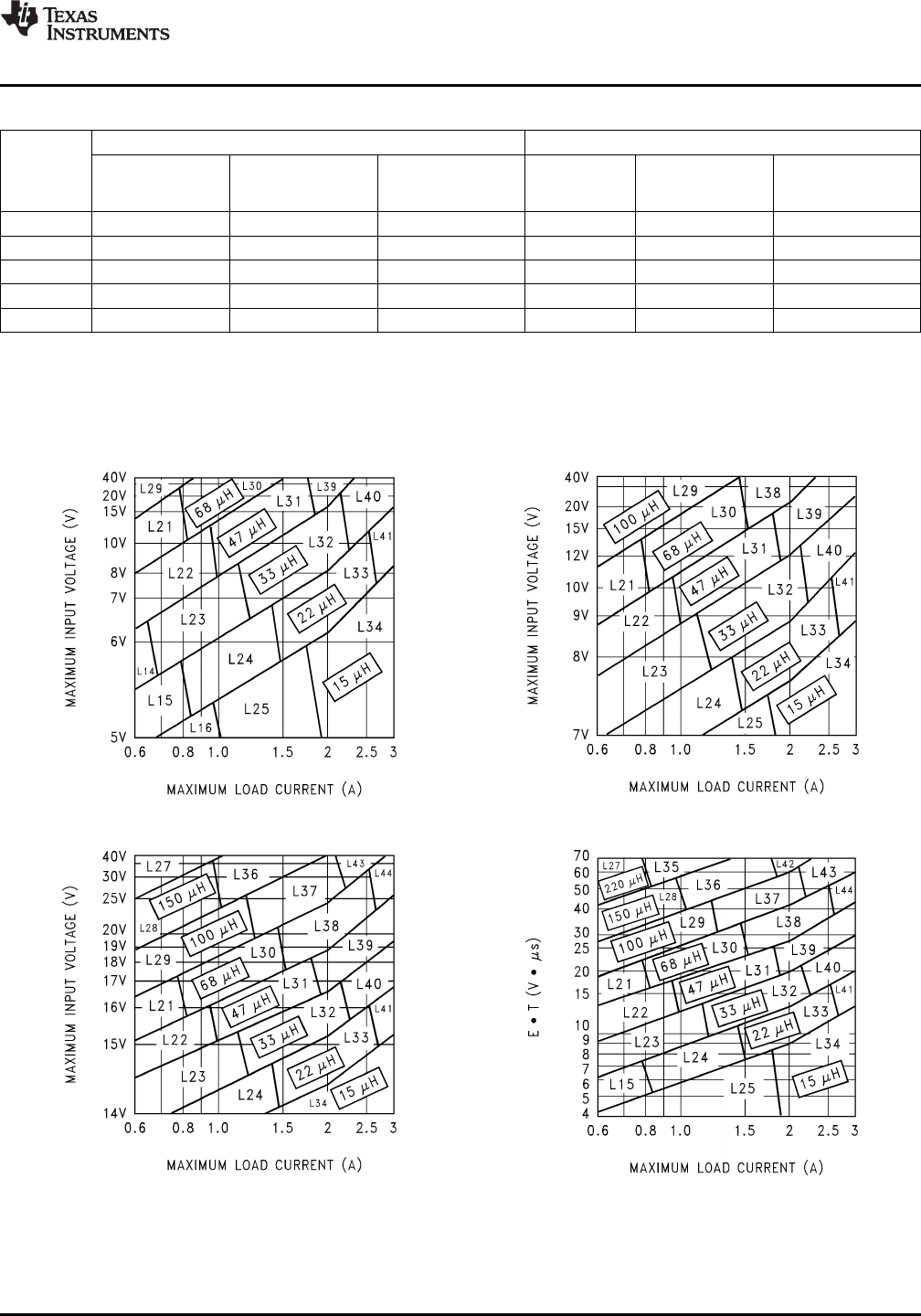
LM2596 Series Buck Regulator Design Procedure
INDUCTOR VALUE SELECTION GUIDES
(For Continuous Mode Operation)
Figure 21. LM2596-3.3 Figure 22. LM2596-5.0
Figure 23. LM2596-12 Figure 24. LM2596-ADJ
Copyright © 1999–2013, Texas Instruments Incorporated Submit Documentation Feedback 15
Product Folder Links: LM2596