
Datasheet


Evaluation Board
www.ti.com
9 Evaluation Board
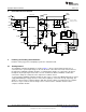
The evaluation board shows how the LM10010 is used to control the LM21215A-1. However, the
LM10010 can be run independently without the LM21215A-1 by applying the supply voltage through P2
and jumpering pins 2 and 3. The IDAC output current can be observed at the IDAC pin with the jumper
removed from FB.
Additionally, the output voltage and range of the module can be adjusted by replacing components on the
board. However, this is not as simple as replacing the feedback resistors R
FB1
and R
FB2
. A change in the
feedback resistors may change the compensation network for the LM21215A-1 and this may require
adjustments in values for C
C1
, C
C2
, C
C3
, R
C1
, and R
C2
. For further guidance with component selection, see
the LM21215A-1 data sheet and evaluation board application reports
10 Control Software
The LM10010 evaluation board comes with a communications dongle and software to control the output
voltage. This section describes software features and modes of operation. The software has a built-in
calculator to determine the feedback resistor values for a given range and resolution of operation. This is
only used when the user decides to remove the existing default resistor feedback values and determines
the LM21215A-1's compensation is correct for the new feedback resistors. The default or updated values
are used to calculate expected output voltages of the point of load regulator. Buttons are used to select
one of two modes of operation. First, the user can set a constant output voltage for the point of load with
either a voltage or a code. Second, the output can be changed dynamically, ramping through different
voltages as the LM10010 counts through a preset sequence. The LM10010 software panel is shown in
Figure 3 below.
Figure 3. LM10010 Evaluation Software Panel
10.1 Resistance Calculator
As mentioned before, this is an optional section that can be used to calculate new resistance values for
R
FB1
and R
FB2
. If the user decides to change the range of the output voltage (from 0.7V to 1.1V) to a
different range, then R
FB1
and R
FB2
should be replaced with new values. If new values are selected, the
compensation for the LM21215A-1 may need to be adjusted as well. As shown in Figure 4, the user can
set the minimum voltage and the maximum voltage in the desired range. The calculator then determines
the proper values for the feedback resistors. The button at the bottom can convert the calculated resistor
values to the nearest 1% resistor values available. Another button in the panel can transfer these values
to the Board Values panel to calculate the expected output voltage when in operation.
6
AN-2176 LM10010 Evaluation Board SNVA498B–July 2011–Revised May 2013
Submit Documentation Feedback
Copyright © 2011–2013, Texas Instruments Incorporated