
Datasheet


Control Software
www.ti.com
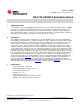
Figure 9. LM10010 Set Dynamic Voltage Panel
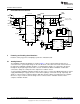
10.6 Plotter
A plotter is provided to show the output voltage of the board. This is a simple diagnostic tool and only
shows the expected output voltage since there are no measurement tools or communications from the
board to the computer. In the set constant voltage mode, the plotter is automatically updated. In the set
dynamic voltage mode, the plotter is updated by the update plot button. Figure 10 shows the Plotter Panel
of the LM10010 software. Vout Plot box shows the expected output voltage, the Code Plot box shows the
current code, and the Count Delay box shows the delay between updates in the count used in the Set
Dynamic Voltage panel. In this example, the count starts at code 0, and ends at code 63, with an
increment code of 4.
Figure 10. LM10010 Plotter Panel
10
AN-2176 LM10010 Evaluation Board SNVA498B–July 2011–Revised May 2013
Submit Documentation Feedback
Copyright © 2011–2013, Texas Instruments Incorporated