
User manual


Chapter 1
SNAU150–September 2013
LDC1000 Evaluation Module
1.1 Overview
The LDC1000 Evaluation Module is designed to provide an example LC tank and coil structure
application, to interface to a host computer. The module can be used independently of the GUI by the on-
board embedded LED, which demonstrates threshold detection.
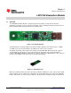
Figure 1-1. Evaluation Module
The EVM includes an example PCB sensor which is 14mm in diameter and contains 2 layers. A 100pF
1% COG cap is connected, in parallel, to the PCB coil, in order to form an LC tank.
The EVM is perforated at two locations: One between Coil and LDC1000, which provides the option to
snap the PCB coil and connect a custom coil required in the application. The second perforation is
between LDC1000 and MSP430, and provides the option to connect the LDC1000+Sensor into a different
system or use multiple of such sensors in one system for prototyping.
Figure 1-2. LDC1000+Sensor
When the evaluation module first powers up from the USB port, it will flash a series of green and red LED
lights to indicate self-test. When self-test is finished, the green LED indicates the status of the LDC1000
INT pin. When INT is asserted, the green LED is lit. By default, INT is configured for threshold detection.
2
LDC1000 Evaluation Module SNAU150–September 2013
Submit Documentation Feedback
Copyright © 2013, Texas Instruments Incorporated