LDC1000 Evaluation Module User's Guide Literature Number: SNAU150 September 2013
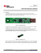
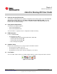
Chapter 1 SNAU150 – September 2013 LDC1000 Evaluation Module 1.1 Overview The LDC1000 Evaluation Module is designed to provide an example LC tank and coil structure application, to interface to a host computer. The module can be used independently of the GUI by the onboard embedded LED, which demonstrates threshold detection. Figure 1-1. Evaluation Module The EVM includes an example PCB sensor which is 14mm in diameter and contains 2 layers.
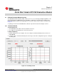
Chapter 2 SNAU150 – September 2013 Quick Start Guide LDC1000 Evaluation Module 2.1 LDC1000 Evaluation Module Overview The LDC1000 Evaluation Module (EVM) enables the user to test out analog and digital capabilities of the LDC1000 Inductance-to-Digital Converter. The EVM is a USB device used with a host computer and accessed using the Inductive Sensing Graphical User Interface (GUI) software, which is documented in Chapter 3.
LDC1000 Evaluation Module Overview www.ti.com Reloading the Device If the EVM is disconnected from the host at any time, simply reconnect the device and the GUI will automatically discover and re-establish the streaming abilities with the device. Configuring the Device Manually 1. The GUI puts the device in streaming mode by default. Click on "Stop" in the Streaming Section to stop streaming. Figure 2-2. Stop Streaming 2. Click on the "Configuration Section" icon in the main window toolbar. Figure 2-3.
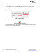
LDC1000 Evaluation Module Overview www.ti.com Figure 2-4. Configuration Section Saving Device Configuration 1. Click on the "Save" icon in the toolbar. Figure 2-5. Save Icon 2. Type a name for the file. Configuring the Device with Configuration File Defaults 1. The GUI puts the device in streaming mode by default. Click on "Stop" in the Streaming Section to stop streaming. 2. Click on the "Open" icon in the toolbar. Figure 2-6. Open Icon 3. Select the configuration file.
LDC1000 Evaluation Module Overview www.ti.com 4. After the configuration file is loaded, current values are written once to all supported registers. To restore defaults defined in the configuration file, click on Restore Defaults to write all current registers with the new configuration file defaults. Figure 2-7.
Chapter 3 SNAU150 – September 2013 Inductive Sensing GUI User Guide 3.1 Inductive Sensing GUI Overview The inductive sensing GUI provides graphical configuration and streaming support for the LDC1000. The GUI package includes drivers for use with the LDC1000 Evaluation Modules (EVM). The EVM provides a device abstraction layer for the GUI to communicate with the LDC1000 through SPI, and includes other extended functionality. 3.
Connecting and Disconnecting www.ti.com Name Description Connection Information Indicates whether an EVM is connected to the PC, and if so, provides details of the connected device. Icon • EVM is connected • EVM is disconnected 3.
Register Settings www.ti.com Figure 3-2. Configuration Section In the configuration window, select the parameter to change. When entering the comparator thresholds, press ENTER to confirm the change. Changes are applied immediately. Press “Read All” to refresh all configuration, status, and data. Press “Restore Defaults” to write values from the default column (if they exist) to the current register value. 3.
Data Streaming www.ti.com Figure 3-3. Register Settings Double-click on a register in the table to read/write. If a register is read only, the selected register is read immediately and the table value updated. If the register is read/write, a dialog pops up and the user can choose a new register value. If the value is not changed, it will default to a read. Figure 3-4. Read/Write Register Dialog Press “Read All” to refresh all configuration, status, and data.
Data Streaming www.ti.com Figure 3-5. Streaming Configuration The sampling rate can only be set when streaming is stopped. 3.10.1 Average, Point, Min, Max Values Average is the default display type. To toggle between sample point, min, and max values, right-click the display.
Saving and Loading www.ti.com 3.10.3 Threshold Display To display Rp Thresholds, right-click the plot and select “Toggle Markers.” Figure 3-7. Toggling Markets 3.11 Saving and Loading 3.11.1 Configurations Configurations can be saved and loaded. To save a configuration, click on the "Save" icon. To load a configuration, click on the "Open" icon. Configurations include all register names, current values, and default values. They are saved in CommaSeparated Files (*.
Saving and Loading www.ti.com Figure 3-8.
Chapter 4 SNAU150 – September 2013 Schematics 4.1 LDC1000 Schematics Figure 4-1. Layout Figure 4-2.
LDC1000 Schematics www.ti.com Figure 4-3.
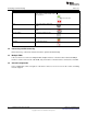
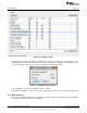
Chapter 5 SNAU150 – September 2013 Bill of Materials Designator Quantity Description Manufacturer Part Number C1 1 CAP, CERM, 2.2uF, 10V, +/-10%, X5R, 0603 Kemet C0603C225K8PACTU C2 1 CAP CER 10UF 10V 10% X5R 0603 TDK Corporation C1608X5R1A106K080AC C3, C5, C11, C12, C16, C19 6 CAP CER 0.1UF 16V 5% X7R 0402 Murata Electronics North America GRM155R71C104JA88D C4 1 CAP, CERM, 0.
www.ti.com Designator Quantity Description Manufacturer Part Number U1 1 Micropower 150 mA LowNoise Ultra Low-Dropout Regulator, 5-pin SOT-23, Pb-Free Texas Instruments LP2985AIM5-3.3/NOPB U2 1 4-CHANNEL ESDPROTECTION ARRAY FOR HIGH-SPEED DATA INTERFACES, DRY006A Texas Instruments TPD4E004DRY U3 1 MCU Texas Instruments MSP430F5528IRGCR U4 1 Inductance to Digital Converter Texas instruments LDC1000 Y1 1 CRYSTAL 24.000MHZ 18PF SMD Abracon Corporation ABMM-24.
IMPORTANT NOTICE Texas Instruments Incorporated and its subsidiaries (TI) reserve the right to make corrections, enhancements, improvements and other changes to its semiconductor products and services per JESD46, latest issue, and to discontinue any product or service per JESD48, latest issue. Buyers should obtain the latest relevant information before placing orders and should verify that such information is current and complete.