
Datasheet


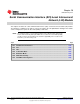


* Dotted vertical lines indicatethe receive edges for the Master
* ENABLE_HIGHZ is set to ‘0’ in Slave SPI
VCLK
SPICLK
SPIENA
Write to
SPIDAT
Write to
SPIDAT
SPISCS
SPISIMO
SPISOMI
Master
Slave
* De-activation of SPIENA pin is controlled by the Slave.
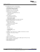
SPISOMI
SPISIMO
SPICLK
SPIENA
VCLK
Write to
SPIDAT
* Dotted vertical lines indicate the receive edges
www.ti.com
MibSPI Pin Timing Parameters
Figure 27-95. SPI/MibSPI Pins During Master Mode in 4-Pin with SPIENA Configuration
Figure 27-96. SPI/MibSPI Pins During Master/Slave Mode with 5-Pin Configuration
1339
SPNU562–May 2014 Multi-Buffered Serial Peripheral Interface Module (MibSPI) with Parallel Pin
Option (MibSPIP)
Submit Documentation Feedback
Copyright © 2014, Texas Instruments Incorporated