
Datasheet


Table Of Contents
1 MW 50 kW
52.6316 kW
50 kW
2.7778 kW
1 MW
7
3
2
6
4 1
A1
INA148
–15 V
V
O
+15 V
Typical CMR: 50 Hz = 59 dB
60 Hz = 61 dB
400 Hz = 78 dB
NOTE: (1) Metallized polypropylene, ±5% tolerance.
C
1
4.7 µF
250 V
(1)
C
2
4.7 µF
250 V
(1)
V
CM
= 200 Vpk
V
+IN
V
–IN
V = (V – V )
O
+IN –IN
1 MW 50 kW
52.6316 kW
50 kW
2.7778 kW
1 MW
–V
S
V
+IN
4
3
2
6
A1
INA148
V
O
V
–IN
0.22 µF
1
V
REF
+V
S
–V
S
+V
S
7
U2:
OPA132 for V
S
= ±5 V to ±15 V
OPA340 for V
S
= ±2.5 V
1 MW
U1
f
C
» 0.75 Hz HPF
2
3
U2
4
7
6
V
O
= (V
+IN
– V
–IN
) + V
REF
INA148-Q1
SBOS472A – MARCH 2009– REVISED OCTOBER 2011
www.ti.com
Source impedances (or shunts) greater than 5 kΩ are not recommended, even if they are "perfectly"
compensated. This is because the internal resistor network is laser-trimmed for accurate voltage divider ratios,
but not necessarily to absolute values. Input resistors are shown as 1 MΩ, however, this is only their nominal
value.
In practice, the input resistors' absolute values may vary by as much as 30%. The two input resistors match to
about 5%, so adding compensating resistors greater than 5 kΩ can cause a serious mismatch in the resulting
resistor network voltage divider ratios, thus degrading CMR.
Attempts to extend the INA148 input voltage range by adding external resistors is not recommended for the
reasons described in the previous paragraph. CMR suffers serious degradation unless the resistors are carefully
trimmed for CMR and gain. This is an iterative adjustment and can be tedious and time consuming.
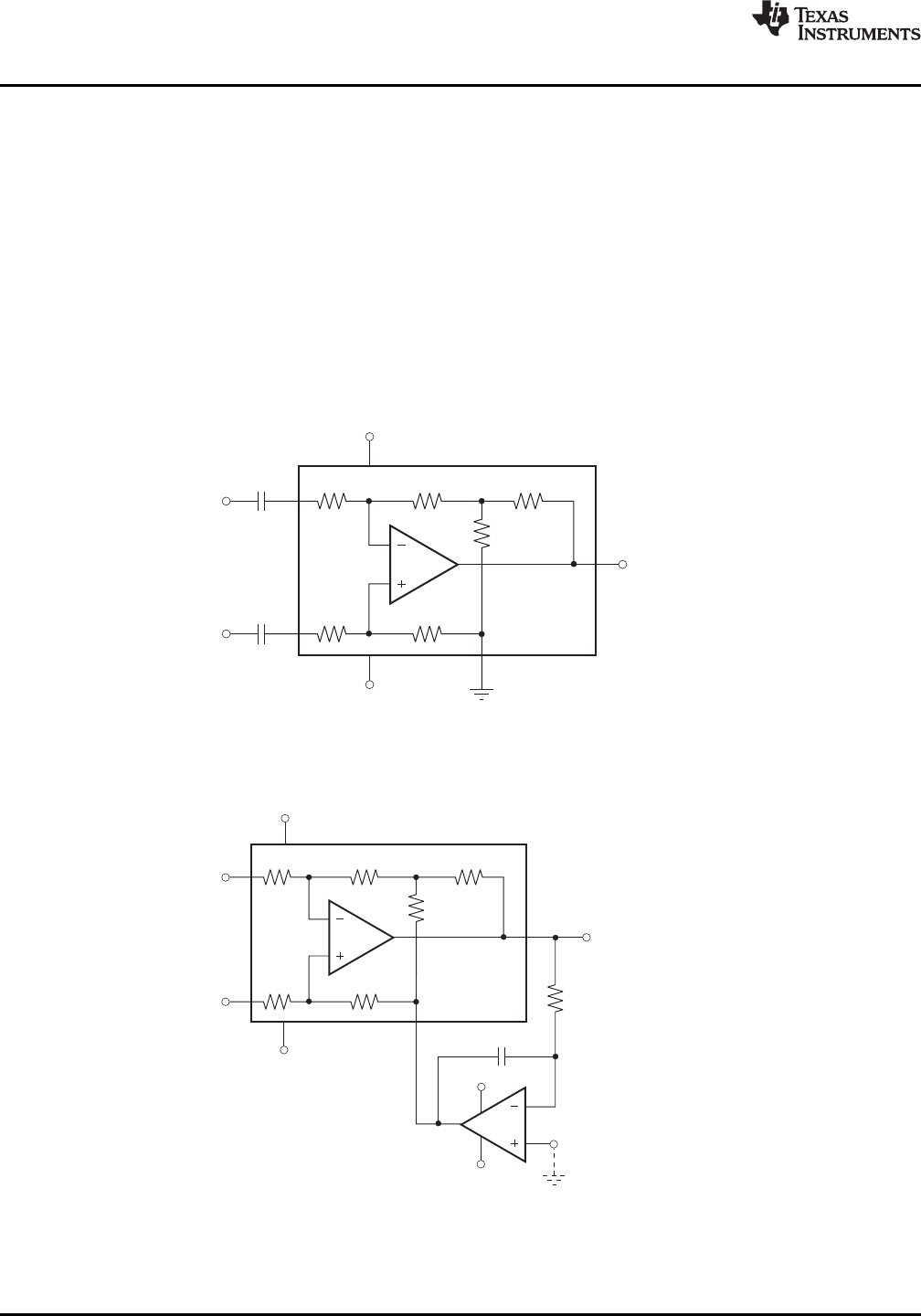
Typical Application Circuits
Figure 5 through Figure 9 show typical application circuits for the INA148.
Figure 5. AC-Coupled Difference Amplifier
Figure 6. Quasi-AC-Coupled Differential Amplifier
12 Submit Documentation Feedback Copyright © 2009–2011, Texas Instruments Incorporated
Product Folder Link(s): INA148-Q1