
User's Manual
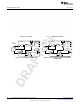
Table Of Contents
- Table of Contents
- 1 Gas Sensor Platform Reference Design User's Guide
- 2 Features
- 3 Hardware Description
- 4 Antenna Simulations
- 5 Schematics and Bill Of Materials
- 6 Layout
- 7 Practical Applications
- A SAT0009 Power Board Files
- Important Notices
- Important Notices

www.ti.com
CO Sensor Example
1.2 CO Sensor Example
The following example uses the CO sensor from the Alphasense CO-AF series (see Section 1.3.1).
A change in µA current of the sensor indications a change in gas concentration. The LMP91000
processes the current and uses the linear TIA stage to convert the current to analog voltage (see
Figure 1-1). The analog voltage is then sent to CC2541. The CC2541 then converts the raw analog
voltage to a digital signal through a 12-bit ADC and transmits the signal through the Bluetooth radio to an
iOS device. The iOS device then performs postprocessing.
1.2.1 Postprocessing Steps as Implemented in the iOS
• Covert voltage (binary to decimal).
– In this example, we assume that CC2541 transmits 019Fh in its VOUT field. iOS software converts
this hexadecimal voltage into a decimal value:
019Fh = 415 (8)
• Since the ADC is inside the CC2541 is a 12-bit resolution (2s complementary).
– Thus the ADC resolution inside CC2541:
2.5 V / (2
11
-1) = 0.001221 (9)
– Note: LM4120 provides a fixed 2.5V precision reference to both LMP91000 and CC2541 in this
reference platform and thus we have used 2.5 V above to calculate the ADC resolution inside
CC2541 .
• Multiply the decimal value from Equation 8 with the ADC resolution:
415 × 0.001221 = 0.506 V (10)
(V
ref_div
–V
out
) / (RTIA) = - I
we_fresh air
• As I
we
is flowing out of the TIA in case of CO sensor, then the V
ref
divider should be set to 20% of V
ref
.
• RTIA above is set to 7000.
• Thus current at pin WE (I
we
) flowing out of the TIA is ~857nA (fresh air calibration). (11)
• Based on the CO-AF specification, the sensitivity of the sensor is 55-90nA/ppm. In the iOS software,
the sensitivity is set to 70nA/ppm (~average of the range).
– 857nA × 70nA/ppm= ~12ppm
• Note: The RTIA for the CO-AF sensor is set to 7000. This ensures that the full range of the CO-AF
sensor (0-5000ppm) can be utilized without clipping.
1.3 Supported Sensor Types
The Gas Sensor Platform from TI can be used either with a 3-lead amperometric cell (not included) (see
Figure 1-4) and a 2-lead galvanic cell (not included) in potentiostat configuration (see Figure 1-5) by a
minor resistor change shown in Figure 5-4.
• For a 3-lead amperometric cell (CO), R43 must be un-installed.
• For a 2-lead galvanic cell (O
2
) R43 must be installed.
9
SNOA922–April 2013 Gas Sensor Platform Reference Design User's Guide
Submit Documentation Feedback
Copyright © 2013, Texas Instruments Incorporated