
User's Manual
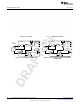
Table Of Contents
- Table of Contents
- 1 Gas Sensor Platform Reference Design User's Guide
- 2 Features
- 3 Hardware Description
- 4 Antenna Simulations
- 5 Schematics and Bill Of Materials
- 6 Layout
- 7 Practical Applications
- A SAT0009 Power Board Files
- Important Notices
- Important Notices

Introduction
www.ti.com
Control Amplifier A1 — A1 is a differential amplifier used to compare the potential between WE and RE.
The error signal is amplified and applied to the CE. Changes in the impedance between the WE
and RE cause a change in the voltage applied to CE in order to maintain the constant voltage
between WE and RE.
Temperature Sensor — An on-board temperature sensor provides a ±3˚C accuracy. The sensor can be
used by an external µC to correct for performance over temperature.
Serial Interface — Calibration and programming is done through the I
2
C digital interface. Calibration and
state-of-health monitoring is enabled by the I
2
C interface. As mentioned before, health monitoring
is very important because chemical cells can degrade over time.
1.1.2 Examples of Firmware and iOS Calculation
This section explains the signal path and signal processing as implemented in the Gas Sensor Platform,
from the sensor to LMP91000, to CC2541 and to the iOS application.
1.1.2.1 O
2
Sensor Example
The following example uses the O
2
sensor from the Alphasense A2 series (see Section 1.3.1).
A change in µA current of the sensor indications a change in gas concentration. The LMP91000
processes the current and uses the linear TIA stage to convert the current to analog voltage (see
Figure 1-1). The analog voltage is then sent to CC2541. The CC2541 then converts the raw analog
voltage to a digital signal through a 12-bit ADC and transmits the signal through the Bluetooth radio to an
iOS device. The iOS device then performs postprocessing.
1.1.2.1.1 Postprocessing Steps as Implemented in the iOS
• Covert voltage (binary to decimal).
– In this example, we assume that CC2541 transmits 0348h in its VOUT field. iOS software converts
this hexadecimal voltage into a decimal value:
0348h = 840 (3)
• Since the ADC is inside the CC2541 is a 12-bit resolution (2s complementary).
– Thus the ADC resolution inside CC2541:
2.5 V / (2
11
-1) = 0.001221 (4)
– Note: LM4120 provides a fixed 2.5V precision reference to both LMP91000 and CC2541 in this
reference platform and thus we have used 2.5 V above to calculate the ADC resolution inside
CC2541 .
• Multiply the decimal value from Equation 8 with the ADC resolution:
840 × 0.001221 = 1.025 V (5)
(V
ref_div
–V
out
) / (RTIA) = I
we_fresh air
• V
ref_div
here is 67% of V
ref
.
• RTIA above is set to 7000.
• Thus current at pin WE (I
we
) flowing into the TIA is ~91 µA (fresh air calibration). (6)
• To change the O
2
concentration, if you exhale (breathe out) on the O
2
sensor; the VOUT would
increase. Let's assume that CC2541 transmits 03B0h in its VOUT field. 03B0h will translate to 944 in
decimal. (see Equation 8).
– 944 × 0.001221 = 1.152 V
• Thus current at pin WE (I
we
) flowing into the TIA in this case would be: (1.667– 1.152) / 7000 =
73.5 µA
• In Equation 11, the calibrated fresh air WE (I
we
) value is 91 µA. For calibration, this can be set to
correspond - 20.9%.
• When we exhale (breathe out) on the O
2
sensor; the normalized O
2
percentage would then be:
(73.5 × 20.9) / 91 = 16.88% (7)
8
Gas Sensor Platform Reference Design User's Guide SNOA922–April 2013
Submit Documentation Feedback
Copyright © 2013, Texas Instruments Incorporated