
User's Manual
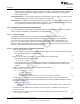
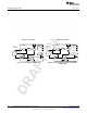
Table Of Contents
- Table of Contents
- 1 Gas Sensor Platform Reference Design User's Guide
- 2 Features
- 3 Hardware Description
- 4 Antenna Simulations
- 5 Schematics and Bill Of Materials
- 6 Layout
- 7 Practical Applications
- A SAT0009 Power Board Files
- Important Notices
- Important Notices

www.ti.com
Introduction
Figure 1-1. Sensor Design
1.1.1 Fundamental Blocks of LMP91000:
Transimpedance Amplifier — TIA provides an output voltage that is proportional to the cell current. TIA
provides seven programmable internal-gain resistors and allows the external-gain resistor to
connect to the LMP91000.
(V
ref_div
–V
out
) / (RTIA) = I
we
(1)
V
out
= (V
ref_div
) – (RTIA × I
we
) (2)
Input — The LMP91000 provides a 3-electrode solution — counter electrode (CE), reference electrode
(RE), working electrode (WE) (see Figure 1-4), as well as a 2-electrode solution — short the CE
and RE (see Figure 1-5).
Variable Bias — Variable bias provides the amount of bias voltage required by a biased gas sensor
between RE and WE. This bias voltage can be programmed to be 1% to 24% of the supply, or it
can be VREF. The bias can also be negative or positive depending on the type of sensing element.
V
ref
Divider — This is the voltage at the noninverting pin at TIA. This voltage can be programmed to be
either 20%, 50%, or 67% of the supply, or it can be VREF. The V
ref
Divider provides the best use
of the full-scale input range of the analog-to-digital converter (ADC) and sufficient headroom for the
counter electrode of the sensor to swing in case of sudden changes in the gas concentration.
• How to select the appropriate V
ref
divider:
– If the current at pin WE (I
we
) is flowing into the TIA, then the V
ref
divider should be set to 67%
of V
ref
.
– If I
we
is flowing out of the TIA, then the V
ref
divider should be set to 20% of V
ref
.
• Assume V
ref_divider
is set to 20% of V
ref
.
• Assume Variable Bias is set to 2% of V
ref
.
• Assume V
ref
= 4.1V.
The V
ref
divider in that case would be 0.82 V. The noninverting input to A1 woul;d be
0.902 V, which is 22% of V
ref
.
7
SNOA922–April 2013 Gas Sensor Platform Reference Design User's Guide
Submit Documentation Feedback
Copyright © 2013, Texas Instruments Incorporated