
User's Manual
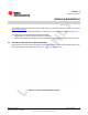
Table Of Contents
- Table of Contents
- 1 Gas Sensor Platform Reference Design User's Guide
- 2 Features
- 3 Hardware Description
- 4 Antenna Simulations
- 5 Schematics and Bill Of Materials
- 6 Layout
- 7 Practical Applications
- A SAT0009 Power Board Files
- Important Notices
- Important Notices

www.ti.com
Getting Started
Figure 3-2. CR2032 Battery
By default the Gas Sensor Platform supports the 3-lead amperometric cell (R43 not installed, see
Section 1.3). By default, the firmware and iOS software support the Alphasense CO-AF sensor. TI
recommends installing the CO-AF sensor (not included) from Alphasense into the socket on the SAT0010
board (see Figure 3-2).
1. Install the sensor onto the platform (see Figure 3-1).
2. Load the CR2032 (not included in the kit) into the coin-cell holder on the SAT0009 board.
3. Turn the on/off switch to the right (with respect to the orientation shown in Figure 3-3).
NOTE: A blue LED flashes when the default firmware is loaded.
4. Download the application from the App Store.
5. Use an iOS device to access the Gas Sensor Platform and interface with the platform (see
Section 7.1).
6. If needed, connect the CC-DEBUGGER (not included in the kit) to the 10-pin header as shown in
Figure 3-3. If changes to the default firmware are needed, see Section 7.2.
Figure 3-3. System Running With LED Flashing
17
SNOA922–April 2013 Hardware Description
Submit Documentation Feedback
Copyright © 2013, Texas Instruments Incorporated