Gas Sensor Platform Reference Design User's Guide User's Guide Literature Number: SNOA922 April 2013 WEBENCH is a registered trademark of Texas Instruments. SmartRF is a trademark of Texas instruments. iPhone, iPad, iPhone 4S, iPad 3 are registered trademarks of Apple Inc. App Store is a trademark of Apple Inc. (service mark). Embedded Workbench is a registered trademark of IAR Systems. I2C is a trademark of NXP. Bluetooth is a registered trademark of SIG, Inc.
Contents 1 Gas Sensor Platform Reference Design User's Guide 1.1 1.2 1.3 2 Features 2.1 2.2 2.3 2.4 3 4 5.2 6 2 ......................................................................................... 25 .............................................................................................................................. 32 SAT Gas Sensor Platform With BLE .................................................................................... 32 6.1.1 SAT0009 (Power Board) Layer Plots ....
www.ti.com List of Figures 1-1. Sensor Design ............................................................................................................... 7 1-2. CO Setup..................................................................................................................... 9 1-3. O2 Setup ...................................................................................................................... 9 1-4. 3-Lead Amperometric Cell...............................................
www.ti.com List of Tables 4 4-1. Antenna Simulations Results Without Battery Board ................................................................. 22 5-1. Power Section BOM 26 5-2. BLE Section BOM 29 ...................................................................................................... ........................................................................................................
Chapter 1 SNOA922 – April 2013 Gas Sensor Platform Reference Design User's Guide 1.1 Introduction The intent of this user's guide is to describe in detail the Gas Sensor Platform with Bluetooth ® LowEnergy Reference Design from Texas Instruments. After reading this user's guide, a user should better understand the features and usage of this reference design platform.
Introduction www.ti.com The Gas Sensor Platform with Bluetooth low-energy (BLE) is intended as a reference design that customers can use to develop end-products for consumer and industrial applications to monitor gases like carbon monoxide (CO), oxygen (O2), ammonia, fluorine, chlorine dioxide etc. . BLE adds a wireless feature to the platform that enables seamless connectivity to an iPhone® or an iPad®.
Introduction www.ti.com Figure 1-1. Sensor Design 1.1.1 Fundamental Blocks of LMP91000: Transimpedance Amplifier — TIA provides an output voltage that is proportional to the cell current. TIA provides seven programmable internal-gain resistors and allows the external-gain resistor to connect to the LMP91000.
Introduction www.ti.com Control Amplifier A1 — A1 is a differential amplifier used to compare the potential between WE and RE. The error signal is amplified and applied to the CE. Changes in the impedance between the WE and RE cause a change in the voltage applied to CE in order to maintain the constant voltage between WE and RE. Temperature Sensor — An on-board temperature sensor provides a ±3˚C accuracy. The sensor can be used by an external µC to correct for performance over temperature.
CO Sensor Example www.ti.com 1.2 CO Sensor Example The following example uses the CO sensor from the Alphasense CO-AF series (see Section 1.3.1). A change in µA current of the sensor indications a change in gas concentration. The LMP91000 processes the current and uses the linear TIA stage to convert the current to analog voltage (see Figure 1-1). The analog voltage is then sent to CC2541.
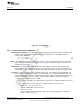
Supported Sensor Types www.ti.com Figure 1-2. CO Setup Figure 1-3. O2 Setup VDD VREF 3-Lead Electrochemical Cell CE + A1 LMP91000 SCL VARIABLE BIAS VREF DIVIDER I2C INTERFACE AND CONTROL REGISTERS SDA 2-wire Sensor such as Oxygen CE + A1 MENB - CE SCL VARIABLE BIAS VREF DIVIDER I2C INTERFACE AND CONTROL REGISTERS SDA MENB - VE- RE RE RE TEMP SENSOR WE WE NC DGND TEMP SENSOR VE+ VOUT + - WE - DGND VOUT + TIA RLoad TIA RLoad RTIA C1 RTIA C2 AGND Figure 1-4.
Supported Sensor Types www.ti.com 1.3.1 WEBENCH® Support TI recommends that customers use WEBENCH for their sensor-type design. Refer to Figure 1-6, Figure 17, and the WEBENCH open design tool at http://www.ti.com/product/lmp91000. The WEBENCH tool lists all of the sensor types compatible with LMP91000. NOTE: The default firmware and the iOS software in the Gas Sensor Platform from TI are designed to support the CO-AF from Alphasense (http://www.alphasense.com/industrialsensors/alphasense_sensors.
Chapter 2 SNOA922 – April 2013 Features 2.
Gas Sensor Platform With BLE Design Features www.ti.com • • • • • • • • Startup into load at 0.7-V input voltage Operating input voltage from 0.7 to 5.5 V Pass-through function during shutdown Minimum switching current 200 mA Output overvoltage, overtemperature, input undervoltage lockout protection Adjustable output voltage from 1.8 to 5.5 V Fixed output voltage versions Small 6-pin SC-70 package CC2541 • Radio – 2.
Featured Applications • 2.2 www.ti.
Block Diagram www.ti.com 2.4 Block Diagram Figure 2-1 shows the block diagram for TI's Gas-Sensor Solution with BLE. Figure 2-1.
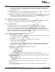
Chapter 3 SNOA922 – April 2013 Hardware Description 3.1 Getting Started Requirements: • Gas sensor: use the recommended CO-AF from Alphasense. • CR2032: Coin-cell • An iOS device: iPhone 4S and newer generations; iPad 3 and newer generations; fifth generation iPod (Apple.com). Download the (?) application from the Apple App Store™ at iTunes.com. NOTE: CC-DEBUGGER is the debug tool to load the firmware to CC2541 (ti.com/tool/cc-debugger).
Getting Started www.ti.com Figure 3-2. CR2032 Battery By default the Gas Sensor Platform supports the 3-lead amperometric cell (R43 not installed, see Section 1.3). By default, the firmware and iOS software support the Alphasense CO-AF sensor. TI recommends installing the CO-AF sensor (not included) from Alphasense into the socket on the SAT0010 board (see Figure 3-2). 1. Install the sensor onto the platform (see Figure 3-1). 2.
Battery Life Calculation 3.2 www.ti.com Battery Life Calculation For battery life calculations, it is highly recommended that the customer reviews CC2541 Battery Life Calculation, SWRA347. It is impossible to use a single metric to compare the power consumption of a BLE device to another device. For example, a device gets rated by its peak current.
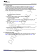
Chapter 4 SNOA922 – April 2013 Antenna Simulations The following data was simulated using the High-Frequency Structural Simulator (HFSS) from ANSYS (www.ansys.com/hfss). The Gas Sensor Platform with BLE platform is a stackup of two 1-inch diameter boards (see Figure 4-1). The goals of the antenna simulations include the following: • Validate that the 2.45-GHz antenna performs as expected. • Estimate the influence of the battery board, by running simulations with and without the battery board. 4.
Simulations With the Battery Board (SAT0009) www.ti.com Figure 4-2. Antenna Simulations With Power Board Figure 4-3.
Simulations With the Battery Board (SAT0009) www.ti.com Figure 4-4. Antenna Simulations Electrical Field Propagation With Power Board The power board (SAT0009) was used in the next simulation to determine if the BLE antenna resulted in an improvement to the performance of SAT0010 (see Figure 4-5, Figure 4-6, and Figure 4-7). Figure 4-5.
Simulations With the Battery Board (SAT0009) www.ti.com Table 4-1. Antenna Simulations Results Without Battery Board Quantity Value Units Max U 0.00043244 W/sr Peak Directivity 1.1138 Peak Gain 0.66408 Peak Realized Gain 0.54344 Radiated Power 0.0048793 W Accepted Power 0.0081833 W Incident Power 0.01 W Radiation Efficiency 0.59625 Front-to-Back Ratio Not Applicable Decay Factor 0 Figure 4-6.
Simulations With the Battery Board (SAT0009) www.ti.com Figure 4-7. Antenna Simulations Field Propagation Without Battery Board Figure 4-8. Improved Antenna Matching Antenna matching was improved by increasing the inductor from 3 to 5 nH (see Figure 4-8. The increase resulted in a better return loss value of 10 dB.
Summary of Findings 4.2 Summary of Findings • • • 4.3 The battery board does not significantly influence the antenna (see Table 4-1). Good omnidirectional radiation pattern is found. – Low peak gain of 1.2. Antenna radiation efficiency is estimated at 54%. Conclusion • • 4.4 www.ti.com Overall board size is very small. – Reduces the antenna efficiency from an estimated 70% to 54%. – Influences the match of the antenna to become only 6 dB.
Chapter 5 SNOA922 – April 2013 Schematics and Bill Of Materials 5.1 SAT Gas Sensor Platform With BLE 5.1.1 Power Board Schematic and BOM A PDF of the SAT0009 (Power Board) can be found here: http://processors.wiki.ti.com/index.php/File:SAT0009_Rev_E1.pdf. CR2032 COIN CE LL BATTE RY VD D 2 U2 VD D 2 1 VIN C22 10uF 6.3V GN D J2 2 FB EN 1 R16 1M 3 GN D 2 C21 47uF 6.3V 2 1 2 1 C20 0.1uF 10V GN D R17 200 kohm GN D J3 2 1 VO U T 6 2 6 C38 1uF 6.3V 4 C23 10uF 6.
SAT Gas Sensor Platform With BLE www.ti.com Table 5-1. Power Section BOM Comment Description Designator Footprint LibRef Qty BS-7-ND Battery Holder BT1 BATTHOLD-BS-7-CR2032 BS-7-ND 1 GRM155R71A104KA01D Cap Cer 0.1 µF 10 V 10 C20 C402-25RD GRM155R71A104KA01 1 TSW-101-07-G-S Conn Header 1POS C21, J6, J8, J9 JUMP1X1-382650CTR TSW-101-07-G-S 4 GRM188R60J106ME47 Cap Cer 10 µF 6.3 V 20 C22, C23 C603-35X45 GRM188R60J106ME47 2 GRM188R60J1 GRM155R60J105KE190 Cap Cer 1 µF 6.
BLE and AFE Section www.ti.com 5.2 BLE and AFE Section A PDF of the SAT0010 AFE (LMP91000) and BLE (CC2541) can be found here: http://processors.wiki.ti.com/index.php/File:SAT0010_Rev_E1.pdf. VD D _FILT VD D FB1 1 2 BLM15HG102SN1D 1 C7 0.1uF 10V C8 2.2uF 6.3V 2 C6 220pF 50V 2 C5 0.1uF 10V 1 1 1 C4 0.1uF 10V 2 2 C3 0.1uF 10V 2 1 1 C2 0.1uF 10V 2 C1 1uF 6.3V 2 2 2 1 J5 1 C36 1uF 6.
BLE and AFE Section www.ti.com VD D 4 U4 LM4120AIM5-2.5 IN EN 1 3 2 LM4120AIM5-2.5CT-ND C24 0.1uF 16V 2 GN D O UT RE F VR EF 5 GN D 1 1 C26 0.1uF 16V DNP R18 0 ohm VR EF EXPEC TED 2 .5 V C27 56pF 50V 2 C25 0.022uF 16V 2 2 1 1 GN D VD D 1 VD D GN D C28 0.022uF 16V 2 GN D LMP91000SDE/NOPBTR-ND 6 GN D VREF VDD SCL R43 0 ohm 14 RE I2C INTERFACE AND CONTROL REGISTERS LMP91000 Configurable Potentiostat AFE 13 VARIABLE BIAS CE A1 R19 10.
BLE and AFE Section www.ti.com Table 5-2. BLE Section BOM Description Designat or Footprint LibRef Qty ASSY_Option ANTENNA IIFA BLE Antenna IIFA BLE A3 Antenna_IIFA _BLE Antenna 1 No part to order or place at ASSY GRM155R60J105KE19D Cap Cer 1 µF 6.3 V 10% X5R C1, C15, C36 C402-25RD GRM155R60J105KE19D GRM155R71A104KA01D Cap Cer 0.1 µF 10 V 10% X7R C2, C3, C4, C5, C7, C30 C402-25RD GRM1555C1H221JA01D Cap Cer 220 pF 50 V 5% NP0 C6 GRM155R60J225ME15D Cap Cer 2.2 µF 6.
BLE and AFE Section www.ti.com Table 5-2. BLE Section BOM (continued) Description Designat or Footprint LibRef Qty ERJ-2GE0R00X Res 0 Ω 1/10W R1, R2, R4, R5, R6, R8, R9, R13, R14, R18, R22, R43 R402-25RD ERJ-2GE0R00X 12 ERJ-2GE0R00X Res 0 Ω 1/10W R3, R21 R402-25RD ERJ-2GE0R00X 2 CR0402-J/-000G Resistor Chip, Jumper, 0 Ω, 1% R7 R402-25RD CR0402-J/-000G 1 CRCW04022K70FKED Res 2.
BLE and AFE Section www.ti.com NOTE: Capacitors C29 and C32 on SAT0010 provide low-pass filtering to the analog output signals (Vout and C2) from LMP91000. In the schematic, they are placed as placeholders and shown as DNP (Do not populate). During testing of this platform it was noted that a value of .01 µF was most optimized for C29 and C32 for this particular platform. Customers can finetune this selection based on their system design. Figure 5-4. CO - O2 Figure 5-5.
Chapter 6 SNOA922 – April 2013 Layout 6.1 SAT Gas Sensor Platform With BLE 6.1.1 SAT0009 (Power Board) Layer Plots A PDF of the SAT0009 (power board) layer plots can be found here: http://processors.wiki.ti.com/index.php/File:SAT0009_Layer_Plot.PDF. Figure 6-1. Power Board 6.1.2 SAT0010 (AFE and BLE Board) Layer Plots A PDF of the SAT0010 (AFE and BLE board) layer plots can be found here: http://processors.wiki.ti.com/index.php/File:SAT0009_Layer_Plot.PDF.
SAT Gas Sensor Platform With BLE www.ti.com Figure 6-2.
Chapter 7 SNOA922 – April 2013 Practical Applications 7.1 iOS Application Figure 7-1, Figure 7-2, Figure 7-3, Figure 7-4, and Figure 7-5 show the TI BLE Sensor application as used with an iPad. Figure 7-1.
iOS Application www.ti.com Figure 7-2. Locating the Sensors Figure 7-3.
iOS Application www.ti.com Figure 7-4. Connecting to a Sensor Figure 7-5.
Firmware Section www.ti.com 7.2 Firmware Section One of the development platforms for the CC2451 8051 microcontroller is the IAR development platform. See http://www.iar.com/ for information on this platform. To communicate to the development platform through IAR, the CC Debugger is required. See Section 3.1. The CC Debugger must be connected to the 10-pin header on the SAT0010 board.
Firmware Section www.ti.com Figure 7-8. IAR Version in Use Ensure that you are using the version used in Figure 7-8 or a newer version. Figure 7-9. Main Loop Highlight Main.c, as shown in Figure 7-9.
Firmware Section www.ti.com Figure 7-10. Communication Settings The number of times the Bluetooth radio communicates with the iOS application can be easily changed by using the highlighted variable shown in Figure 7-10. Figure 7-11. Sensor Section The firmware has a case statement to easily change from a CO sensor to an O2 sensor, as shown in Figure 7-11. Note the x in front of the CO option.
Firmware Section www.ti.com Figure 7-12. CO Settings All the key configuration settings for LMP91000 have been co-located for easy update to the firmware (see Figure 7-12). Figure 7-13. Adding New Sensor New sensor services can be added to the firmware, as shown in Figure 7-13.
Appendix A SNOA922 – April 2013 SAT0009 Power Board Files A.1 Gerber Files The .zip file for the SAT0009 power board can be found here: http://processors.wiki.ti.com/index.php/File:SAT0009_Rev_E1(Gerbers,_TPS61220)121008A.zip. The .zip file for the SAT0010 AFE and BLE board can be found here: http://processors.wiki.ti.com/index.php/File:SAT0009_Rev_E1(Gerbers,_TPS61220)121008A.zip. A.2 Altium Project Files The .zip file for the SAT0009 power board can be found here: http://processors.wiki.ti.com/index.
Altium Project Files www.ti.com Figure A-2.
EVALUATION BOARD/KIT/MODULE (EVM) ADDITIONAL TERMS Texas Instruments (TI) provides the enclosed Evaluation Board/Kit/Module (EVM) under the following conditions: The user assumes all responsibility and liability for proper and safe handling of the goods. Further, the user indemnifies TI from all claims arising from the handling or use of the goods.
FCC Interference Statement for Class B EVM devices This equipment has been tested and found to comply with the limits for a Class B digital device, pursuant to part 15 of the FCC Rules. These limits are designed to provide reasonable protection against harmful interference in a residential installation. This equipment generates, uses and can radiate radio frequency energy and, if not installed and used in accordance with the instructions, may cause harmful interference to radio communications.
【Important Notice for Users of this Product in Japan】 】 This development kit is NOT certified as Confirming to Technical Regulations of Radio Law of Japan If you use this product in Japan, you are required by Radio Law of Japan to follow the instructions below with respect to this product: 1. 2. 3. Use this product in a shielded room or any other test facility as defined in the notification #173 issued by Ministry of Internal Affairs and Communications on March 28, 2006, based on Sub-section 1.
EVALUATION BOARD/KIT/MODULE (EVM) WARNINGS, RESTRICTIONS AND DISCLAIMERS For Feasibility Evaluation Only, in Laboratory/Development Environments. Unless otherwise indicated, this EVM is not a finished electrical equipment and not intended for consumer use.
IMPORTANT NOTICE Texas Instruments Incorporated and its subsidiaries (TI) reserve the right to make corrections, enhancements, improvements and other changes to its semiconductor products and services per JESD46, latest issue, and to discontinue any product or service per JESD48, latest issue. Buyers should obtain the latest relevant information before placing orders and should verify that such information is current and complete.