
Personal Lift User Manual

www.ti.com
3 EVM Operation
3.1 Default Settings
3.2 Host Processor Interface
3.3 EVM Stacking
EVM Operation
This section covers the operation of the EVM in detail, in order to provide guidance to the user in
evaluating the onboard DAC as well as how to interface the EVM to a specific host processor. Refer to the
DAC8555 datasheet for information about its serial interface and other related topics. The EVM board is
factory-tested and configured.
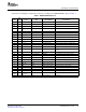
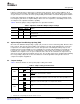
The EVM is set to its factory default configuration as described in Table 2 to operate in 5V mode.
Table 2. Factory Default Jumper Settings
Reference Jumper Position Function
JMP1 CLOSE ENABLE pin is tied to DGND
JMP2 CLOSE LDAC pin is tied to DGND. Software LDAC is used.
JMP3 CLOSE RSTSEL pin is tied to DGND.
JMP4 OPEN RST pin is tied to V
DD
.
V
REF
H is not routed to the inverting input of the op amp for voltage offset with gain of 2
JMP5 OPEN
output.
JMP6 OPEN Output op amp U2 is not configured for a gain of 2.
JMP7 1-2 Analog supply for the DAC8555 is +5V
A
.
JPM8 1-2 Onboard external buffered reference U3 is routed to V
REF
H.
JMP9 1-2 V
REF
L is tied to AGND.
JMP10 1-2 Negative supply rail of U2 op amp is supplied with V
SS
.
JMP11 1-2 DAC output A (V
OUT
A) is routed to J4-2.
JMP12 1-2 DAC output B (V
OUT
B) is routed to J4-4.
JMP13 1-2 DAC output C (V
OUT
C) is routed to J4-6.
JMP14 1-2 DAC output D (V
OUT
D) is routed to J4-8.
JMP15 1-2 J4-1 is connected to the noninverting input of the output op amp U2.
JMP16 1-2 J4-5 is connected to the output of the op amp U2.
The host processor drives the DAC. Thus, proper DAC operation depends on a successful configuration
between the host processor and the EVM board. In addition, properly written code is also required to
operate the DAC.
As discussed earlier, a custom cable can be made specific to the host interface platform. The EVM allows
interface to the host processor through header connector J2 for the serial control signals and the serial
data input. The output can be monitored through header connector J4.
An interface adapter card is also available for specific TI DSP DSKs as well as an MSP430-based
microprocessor (see Section 1.3 of this manual). Using the interface card alleviates the tedious task of
building customized cables and allows easy configuration of a simple evaluation system.
The DAC8555 interfaces with any host processor capable of handling SPI protocols or the popular TI
DSPs. For more information regarding the DAC8555 data interface, please refer to the DAC8555
datasheet .
Stacking multiple EVMS is possible if there is a need to evaluate two DAC8555s, yielding a total of eight
output channels. A maximum of two EVMs can be stacked since the output terminal, J4, dictates the
number of DAC channels that can be connected without colliding. Table 3 shows how the DAC output
channels are mapped into the output terminal, J4, with respect to the jumper positions of JMP11, JMP12,
JMP13, and JMP14.
DAC8555EVM User's Guide16 SLAU204 – December 2006
Submit Documentation Feedback