
User's Manual

Operations that Modify the Contents of the ’F20x/F24x Flash Array
PRELIMINARY
2-4
PRELIMINARY
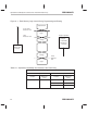
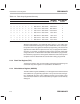
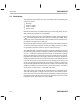
Figure 2–1. Flash Memory Logic Levels During Programming and Erasing
Erase operation
Depletion Mode
Logic 1
1 Margin
0 Margin
Logic 0
VER0
Erase
(Towards logic
Clear
Program
Flash Write
(Towards logic
Reference
level
Inverse Erase
Program operations
Reference Level
VER1
Reference Level
one level)
zero level)
Table 2–1. Operations that Modify the Contents of the Flash Array
Change in Bit Level
Towards Logic 1 Towards Logic 0
Function Reference
Level
Function Reference
Level
Erase (all bits) VER1
Program (selected bits) VER0
Clear (all bits) VER0
Flash-Write (all bits) Inverse Erase