
User's Manual
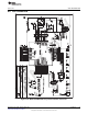
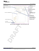

Connector J5
External power connector
for DVCC. Jumper JP3 to
"ext“.
IMPORTANT NOTE:
Rev1.0 of the board
doesn’t has connection
from pin 4 of BOOST to pin
64 of MCU. In order to use
BSL these pin should be
connected by a wire.
Jumper JP2
Open to disconnect LED
D1 LED connected to P1.0
Orient Pin 1 of MSP430 device
Jumpers JP5 to JP10
Close 1-2 to debug in Spy-Bi-Wire
mode
Close 2-3 to debug in 4-wire JTAG
mode
Connector J6
External power connector
to supply DVIO
Jumper JP4
Close if only one power
supply over J5 is used for
VCC and DVI
www.ti.com
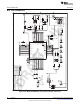
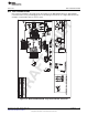
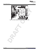
MSP-TS430RGC64C
Figure B-36. MSP-TS430RGC64C Target Socket Module, PCB
85
SLAU278I–May 2009–Revised May 2012 Hardware
Submit Documentation Feedback
Copyright © 2009–2012, Texas Instruments Incorporated