
User manual

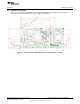


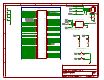


Table Of Contents
49.9
49.9
49.4
49.9
330
GND
330
GND
0.1uF0.1uF
GNDGND
0.1uF0.1uF
75
75
GNDGND
75
75
GND
4700pF
1M
1000pF
R21
R22
R23
R24
D4
R30
D3
R31
C16C17
C18C22
P$1
P$1
P$2
P$2
P$3
P$3
P$6
P$6
P$7
P$7
P$8
P$8
P$9
P$9
P$10
P$10
P$11
P$11
P$14
P$14
P$15
P$15
P$16
P$16
P$1
1
P$2
2
P$3
3
P$4
4
P$5
5
P$6
6
P$7
7
P$8
8
R32
R43
CHASSIS
9
CHASSIS
10
RX+
3
RX-
6
TERM1A
4
TERM1B
5
TERM2A
7
TERM2B
8
TX+
1
TX-
2
R45
R46
C31
R47
C1
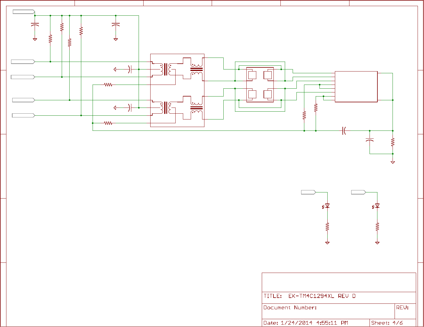
EN0RXI_N/5.3B
EN0RXI_P/5.3B
EN0TXO_N/5.3B
EN0TXO_P/5.3B
PF4/3.2C PF0/3.2C
MCU_3V3/5.2A
A
B
C
D
E
A
B
C
D
E
1 2 3 4 5 6
U10
U13
U14
For Ethernet example Applications:
LED4 is default configured as Ethernet Link OK
LED3 is default configured as Ethernet TX/RX activity
User may re-configure these pins / LED's for any
application usage.
Place pull up resistors and C16-C17 near TM4C MCU.
Place C18 and C22 near pin 2 and pin 7 of U$10
U10 May be populated with either HX1188FNL or HX1198FNL.
HX1198FNL preferred for best Ethernet performance.