Tiva™ C Series TM4C1294 Connected LaunchPad Evaluation Kit EK-TM4C1294XL User's Guide Literature Number: SPMU365A March 2014 – Revised March 2014
Contents 1 Board Overview ................................................................................................................... 4 1.1 1.2 1.3 1.4 1.5 1.6 2 2.2 2.3 Functional Description ...................................................................................................... 7 2.1.1 Microcontroller....................................................................................................... 7 2.1.2 Ethernet Connectivity...............................................
www.ti.com List of Figures 1-1. Tiva C Series Connected LaunchPad Evaluation Board ............................................................... 4 2-1. Tiva Connected LaunchPad Evaluation Board Block Diagram ........................................................ 7 2-2. Default Jumper Locations ................................................................................................. 17 4-1. Connected LaunchPad Dimensions and Component Locations ............................................
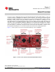
Chapter 1 SPMU365A – March 2014 – Revised March 2014 Board Overview The Tiva™ C Series TM4C1294 Connected LaunchPad Evaluation Board (EK-TM4C1294XL) is a low-cost evaluation platform for ARM® Cortex™-M4F-based microcontrollers. The Connected LaunchPad design highlights the TM4C1294NCPDT microcontroller with its on-chip 10/100 Ethernet MAC and PHY, USB 2.0, hibernation module, motion control pulse-width modulation and a multitude of simultaneous serial connectivity.
Kit Contents www.ti.com 1.1 Kit Contents The Connected LaunchPad Evaluation Kit contains the following items: • Tiva™ C Series TM4C1294 Evaluation Board (EK-TM4C1294XL) • Retractable Ethernet cable • USB Micro-B plug to USB-A plug cable • README First document 1.2 Using the Connected LaunchPad The recommended steps for using the Connected LaunchPad Evaluation Kit are: 1. Follow the README First document included in the kit.
BoosterPacks www.ti.com – For a complete list of BoosterPacks, see the TI MCU LaunchPad web page: http://www.ti.com/launchpad 1.4 BoosterPacks The Connected LaunchPad provides an easy and inexpensive way to develop applications with the TM4C1294NCPDTI microcontroller. BoosterPacks are add-on boards that follow a pin-out standard created by Texas Instruments.
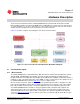
Chapter 2 SPMU365A – March 2014 – Revised March 2014 Hardware Description The Connected LaunchPad includes a TM4C1294NCPDTI microcontroller with an integrated 10/100 Ethernet MAC and PHY. This advanced ARM® Cortex™ M4F MCU has a wide range of peripherals that are made available to users via the on-board accessories and the BoosterPack connectors. This chapter explains how those peripherals operate and interface to the microcontroller.
Functional Description www.ti.com 2.1.2 Ethernet Connectivity The Connected LaunchPad is designed to connect directly to an Ethernet network using RJ45 style connectors. The microcontroller contains a fully integrated Ethernet MAC and PHY. This integration creates a simple, elegant and cost-saving Ethernet circuit design. Example code is available for both the uIP and LwIP TCP/IP protocol stacks. The embedded Ethernet on this device can be programmed to act as an HTTP server, client or both.
Functional Description www.ti.com 2.1.6 BoosterPacks and Headers 2.1.6.1 BoosterPack 1 The Connected LaunchPad features two fully independent BoosterPack XL connectors. BoosterPack 1, located around the ICDI portion of the board, is fully compliant with the BoosterPack standard with the single exception of GPIO pin PA6 (X8-16), which does not provide analog capability. PA6 is located near the bottom of the inner left BoosterPack XL header.
Functional Description www.ti.com Table 2-1.
Functional Description www.ti.com 2.1.6.2 BoosterPack 2 The second BoosterPack XL interface is located near the middle of the board. This interface is fully compliant with the BoosterPack standard, and adds features not covered by the BoosterPack standard that enable operation with additional BoosterPacks. An additional analog signal is provided on the outer left header (X6-9). This signal can be used to monitor the touch panel on the popular Kentec EB-LM4F120-L35 BoosterPack.
Functional Description www.ti.com Table 2-2.
Functional Description www.ti.com 2.1.6.3 Breadboard Connection The breadboard adapter section of the board is a set of 98 holes on a 0.1 inch grid. Properly combined with a pair of right angle headers, the entire Connected LaunchPad can be plugged directly into a standard 300 mil (0.3 inch) wide solder-less breadboard. The right angle headers and breadboard are not provided with this kit.
Functional Description www.ti.com Table 2-3.
Functional Description www.ti.com Table 2-4.
Functional Description www.ti.com Table 2-4.
Power Management www.ti.com 2.1.6.4 Other Headers and Jumpers JP1 is provided to select the power input source for the Connected LaunchPad. The top position is for BoosterPack power; this position also disconnects both USB voltages from the board’s primary 5-volt input. In the top position, the TPS2052B does not limit current so additional care should be exercised. The middle position draws power from the USB connector on the left side of the board near the Ethernet jack.
Power Management www.ti.com 2.2.2 Low Power Modes The Connected LaunchPad demonstrates several low power microcontroller modes. In run mode, the microcontroller can be clocked from several sources such as the internal precision oscillator or an external crystal oscillator. Either of these sources can then optionally drive an internal PLL to increase the effective frequency of the system up to 120 MHz. In this way, the run mode clock speed can be used to manage run mode current consumption.
Debug Interface www.ti.com 2.3.2 External Debugger The connector U6 is provided for the attachment of an external debug adapter such as the IAR J-Link or Keil ULINK. This connector follows the ARM standard 10-pin JTAG pinout. This interface can use either JTAG or SWD if supported by the external debug adapter. 2.3.3 Virtual COM Port When plugged into a USB host, the ICDI enumerates as both a debugger and a virtual COM port.
Chapter 3 SPMU365A – March 2014 – Revised March 2014 Software Development This chapter provides general information on software development as well as instructions for flash memory programming. 3.1 Software Description The TivaWare software provides drivers for all of the peripheral devices supplied in the design. The Tiva C Series Peripheral Driver Library is used to operate the on-chip peripherals as part of TivaWare.
Programming the Connected LaunchPad www.ti.com 3.4 Programming the Connected LaunchPad The Connected LaunchPad software package includes pre-built binaries for each of the example applications. If you installed the TivaWare™ software to the default installation path of C:\ti\TivaWare_C_Series_, you can find the example applications in C:\ti\TivaWare_C_Series\examples\boards\ek-tm4c129xl.
Chapter 4 SPMU365A – March 2014 – Revised March 2014 References, PCB Layout, and Bill of Materials 4.1 References In • • • • • • • • • addition to this document the following references are available for download at www.ti.com. TivaWare for C Series (http://www.ti.com/tool/sw-tm4c) TivaWare Peripheral Driver Library Users' Guide (literature number SPMU298) EK-TM4C1294XL Getting Started Guide (literature number SPMZ858) LM Flash Programmer Tool (http://www.ti.
Component Locations www.ti.com 4.2 Component Locations Figure 4-1 is a dimensioned drawing of the Connected LaunchPad. This figure shows the location of selected features of the board as well as the component locations. Figure 4-1.
Bill of Materials 4.3 www.ti.com Bill of Materials Table 4-1 is the Connected LaunchPad bill of materials list. Table 4-1. Connected LaunchPad Bill of Materials Item Qty Description Mfg Part Number Kemet C1210C102MGRACTU 1 C1 1 Capacitor, 1000pF, 2kV, 20%, X7R, 1210 2 C3, C4, C5, C10, C11, C12, C13, C16, C17, C18, C19, C21, C22, C23, C24, C25, C26, C27, C28, C29, C30, C40, C41, C42, C43, C46 26 Capacitor, 0.
Bill of Materials www.ti.com Table 4-1. Connected LaunchPad Bill of Materials (continued) Item Ref Qty Description Mfg Part Number 27 RESET, USR_SW1, USR_SW2, WAKE 4 Switch, Tact 6mm SMT, 160gf Omron B3S-1000 TM4C1294NCPDT U1 1 Tiva, MCU TM4C1294NCPDT 128 QFP with Ethernet MAC + PHY Texas Instruments 28 Texas Instruments XM4C1294NCPDT 29 U10 1 Transformer, ethernet, 1 to 1.
Chapter 5 SPMU365A – March 2014 – Revised March 2014 Schematic This section contains the complete schematics for the Tiva C Series TM4C1294 Connected LaunchPad.
3 4 5 6 TP4 TARGET_VBUS/3.
1 2 3 4 5 6 +5V X8-2 +3V3 A TSW-110-02-S-D X8-1 GND/1.6B C23 0.1uF GND X8-3 X8-5 X8-7 X8-9 X8-11 X8-13 X8-15 X8-17 X8-19 PE4 PC4 PC5 PC6 PE5 PD3 PC7 PB2 PB3 PE0 PE1 PE2 PE3 PD7 PA6 PM4 PM5 TSW-110-02-S-D X8-4 X8-6 X8-8 X8-10 X8-12 X8-14 X8-16 X8-18 X8-20 C24 0.1uF GND X9-1 X9-3 X9-5 X9-7 X9-9 X9-11 X9-13 X9-15 X9-17 X9-19 A X9-2 GND/1.6B PF1 PF2 PF3 PG0 PL4 PL5 PL0 PL1 PL2 PL3 PM3 PH2 PH3 X9-4 X9-6 X9-8 TARGET_RESET/3.
2 3 4 +5V This is the breadboard connection header. Samtec TSW-149-08-F-S-RA and TSW-149-09-F-S-RE can be used together to create a breadboard connector see the Users Manual for more information. C28 A 0.1uF 5 6 +3V3 1 C27 0.1uF A TSW-149-02-S-D GND PA2 PA3 PA4 PA5 PE0 PE1 PE2 PE3 PE4 PE5 PK0 PK1 PK2 PK3 B VREF+/5.5B GND/2.3C PD5 PD4 PD7 PD6 PD3 PD1 PD0 PD2 PP0 PP1 PB0 TARGET_VBUS/1.6B GND/2.3C PF4 PF0 PF1 PF2 PF3 PA0 PA1 PP4 PP5 PJ0 PJ1 PM7 PM6 PM5 PM4 D +3V3 C TARGET_RESET/2.4D GND/2.
1 2 4 5 6 R21 49.9 R23 C16 0.1uF R22 GND R24 49.9 0.1uF 49.9 49.4 C17 A 3 Place pull up resistors and C16-C17 near TM4C MCU. MCU_3V3/5.2A A GND Place C18 and C22 near pin 2 and pin 7 of U$10 U10 3 75 R43 C22 0.1uF EN0RXI_N/5.3B P$7 P$8 P$10 P$11 P$7 P$3 P$6 P$4 P$5 7 6 P$11 4 P$6 5 P$7 R46 P$6 EN0RXI_P/5.
1 2 3 4 5 6 JP2 can be used to measure MCU current consumption with a multi-meter. +3V3 WAKE A MCU_3V3/4.1A 10k SWITCH_TACTILE Power Control Jumper: TARGET_RESET/3.2D 1) To power from Debug install jumper on pins 5 - 6 2) To power from Target USB install jumper on pins 3 - 4 RESET 3) To power from BoosterPack 5V install jumper on pins 1 - 2 This is also the off position if BoosterPack does not supply power When powered from BoosterPack TPS2052B does not provide current limit protection.
1 2 3 4 5 JTAG PULL-UPS 10k 5.6k 10k R28 R29 6 Use this for JTAG IN from external debugger. See X1 jumpers for information about debug out to an external target. R40 must be removed for debug out. R40 must be instaled for debug in. R1 10k +3V3 DEBUG_VBUS/5.1B MCU_3V3/5.6B TARGET_TCK/SWCLK/1.2A GND U6 TARGET_TMS/SWDIO/1.2B ICDI_TCK R4 10k ICDI_TMS EXTERNAL_DEBUG R5 EXTERNAL_DEBUG pull low to use external debugger to debug the target.
Chapter 6 SPMU365A – March 2014 – Revised March 2014 Revision History This history highlights the changes made to the SPMU365 user's guide to make it an SPMU365A revision. Table 6-1. Revision History SEE Section 2.1.6.
IMPORTANT NOTICE Texas Instruments Incorporated and its subsidiaries (TI) reserve the right to make corrections, enhancements, improvements and other changes to its semiconductor products and services per JESD46, latest issue, and to discontinue any product or service per JESD48, latest issue. Buyers should obtain the latest relevant information before placing orders and should verify that such information is current and complete.