
Datasheet

DS9637A
www.ti.com
SNLS388D –MAY 1998–REVISED APRIL 2013
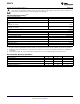
Electrical Characteristics
(1)(2)
Over recommended operating temperature and supply voltage ranges, unless otherwise specified
Symbol Parameter Conditions Min Typ Max Units
V
TH
Differential Input Threshold −7.0V ≤ V
CM
≤ +7.0V
−0.2 +0.2 V
Voltage
(3)
V
TH(R)
Differential Input Threshold −7.0V ≤ V
CM
≤ +7.0V
−0.4 +0.4 V
Voltage
(4)
I
I
Input Current
(5)
V
I
= 10V, 0V ≤ V
CC
≤ +5.5V 1.1 3.25 mA
V
I
= −10V, 0V ≤ V
CC
≤ +5.5V −1.6 −3.25
V
OL
Output Voltage LOW I
OL
= 20 mA, V
CC
= Min 0.35 0.5 V
V
OH
Output Voltage HIGH I
OH
= −1.0 mA, V
CC
= Min 2.5 3.5 V
I
OS
Output Short Circuit Current
(6)
V
O
= 0V, V
CC
= Max −40 −75 −100 mA
I
CC
Supply Current V
CC
= Max, V
I
+ = 0.5V, 35 50 mA
V
I
− = GND
V
HYST
Input Hysteresis V
CM
= ±7.0V (See Curves) 70 mV
(1) Unless otherwise specified Min/Max limits apply across the −55°C to +125°C temperature range for DS9637AM and across the 0°C to
+70°C range for the DS9637ASC. All typicals are given for V
CC
= 5V and T
A
= 25°C.
(2) All currents into the device pins are positive; all currents out of the device pins are negative. All voltages are referenced to ground
unless otherwise specified.
(3) V
DIFF
(Differential Input Voltage) = (V
I
+) − (V
I
−). V
CM
(Common Mode Input Voltage) = V
I
+ or V
I
−.
(4) 500Ω ±1% in series with inputs.
(5) The input not under test is tied to ground.
(6) Only one output at a time should be shorted.
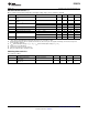
Switching Characteristics
V
CC
= 5.0V, T
A
= 25°C
Symbol Parameter Conditions Min Typ Max Units
t
PLH
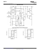
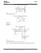
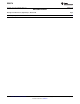
Propagation Delay Time See AC Test Circuit
15 25 ns
Low to High
t
PHL
Propagation Delay Time See AC Test Circuit
13 25 ns
High to Low
Copyright © 1998–2013, Texas Instruments Incorporated Submit Documentation Feedback 3
Product Folder Links: DS9637A