
Datasheet


Table Of Contents
- FEATURES
- Applications
- DESCRIPTION
- Absolute Maximum Ratings
- Recommended Operating Conditions
- Electrical Characteristics
- Setup and Timing Diagrams
- Functional Description
- Application Information
- TYPICAL APPLICATION
- MULTIPLE HOP APPLICATION
- MATRIX SWITCH APPLICATION
- DUAL LINK APPLICATION
- DC AND AC COUPLED APPLICATIONS
- CABLE SELECTION AND INTER-PAIR SKEW
- 28 AWG STP (SHIELDED TWIST PAIRS) DVI / HDMI CABLES RECOMMENDED EQ SETTINGS
- 24 AWG UTP (LOW SKEW UNSHIELDED TWIST PAIRS) CABLES
- General Recommendations
- Typical Performance Characteristics as a Repeater
- Revision History
Coax
Coax
Coax
Coax
Coax
Coax
Data0 +
Data0 -
Pattern Generator
Clk -
Clk +
SMA
SMA
SMA
SMA
RT
SMA
SMA
SMA
SMA
TPA
TPB TPC
Jitter Test Instrument
Coax
Coax
Coax
Coax
SMA
SMA
SMA
SMA
SMA
SMA
Data1 -
Data1 +
Data2 -
Data2 +
AVcc
AVcc
AVcc
AVcc
SMA
Coax
Coax
SMA
DS34RT5110
Coax
Coax
Coax
Coax
VDD
VDD
VDD
VDD
TPD
RT
RT
RT
RT
RT
RT
RT
RT
RT
RT
RT
RT
RT
RTRT
HDMI Cable A
HDMI Cable B
DS34RT5110
www.ti.com
SNLS310G –MARCH 2009–REVISED APRIL 2013
Electrical Characteristics (continued)
Over recommended operating supply and temperature ranges unless otherwise specified. All parameters are ensured by test,
statistical analysis, or design unless otherwise specified
(1)
.
Symbol Parameter Condition Min Typ Max Units
Clock Channel PLL Jitter Generation
Total Output Jitter Clock Path, measured at TPC
TROJ5 0.03 0.045 UIp-p
25 MHz Figure 1
(7)(8)(9)
Total Output Jitter Clock Path, measured at TPC
TROJ6 0.07 0.13 UIp-p
165 MHz Figure 1
(7)(8)(9)
Total Output Jitter Clock Path, measured at TPC
TROJ7 0.08 0.135 UIp-p
225 MHz Figure 1
(7)(8)(9)
Total Output Jitter Clock Path, measured at TPC
TROJ8 0.09 0.14 UIp-p
340 MHz Figure 1
(7)(8)(9)
(7) Parameter is ensured by statistical analysis and/or design.
(8) Deterministic jitter is measured at the differential outputs (TPC of Figure 1), minus the deterministic jitter before the test channel (TPA of
Figure 1). Random jitter is removed through the use of averaging or similar means.
(9) Total Jitter is defined as peak-to-peak deterministic jitter from + 12 times random jitter (ps).
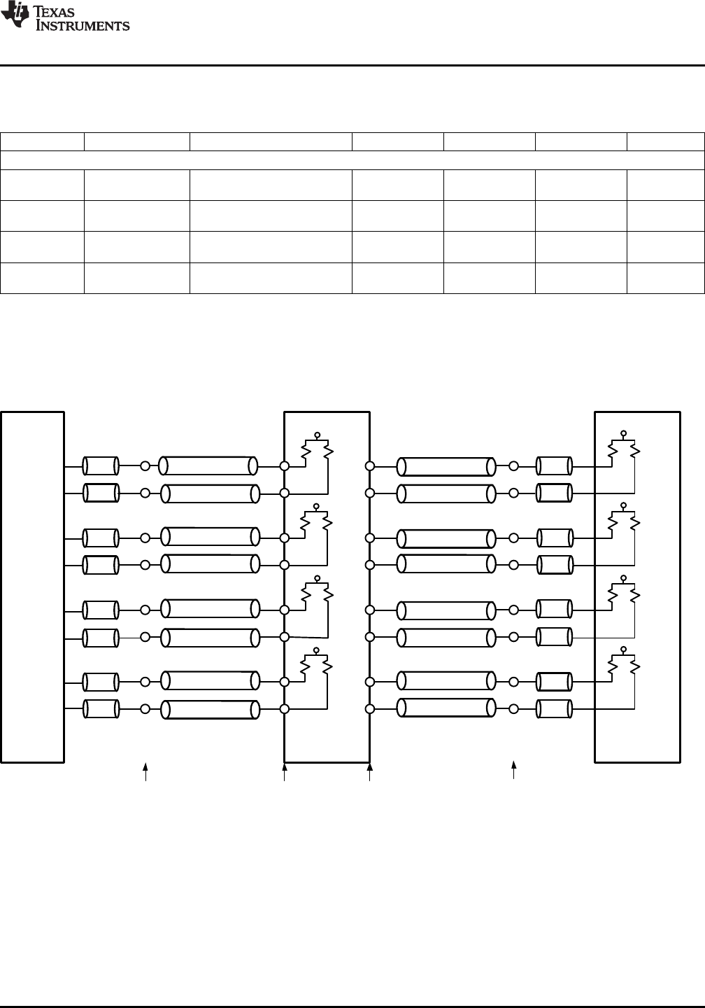
Setup and Timing Diagrams
Figure 1. Test Setup Diagram
Copyright © 2009–2013, Texas Instruments Incorporated Submit Documentation Feedback 7
Product Folder Links: DS34RT5110