
Datasheet


Table Of Contents
- FEATURES
- Applications
- DESCRIPTION
- Absolute Maximum Ratings
- Recommended Operating Conditions
- Electrical Characteristics
- Setup and Timing Diagrams
- Functional Description
- Application Information
- TYPICAL APPLICATION
- MULTIPLE HOP APPLICATION
- MATRIX SWITCH APPLICATION
- DUAL LINK APPLICATION
- DC AND AC COUPLED APPLICATIONS
- CABLE SELECTION AND INTER-PAIR SKEW
- 28 AWG STP (SHIELDED TWIST PAIRS) DVI / HDMI CABLES RECOMMENDED EQ SETTINGS
- 24 AWG UTP (LOW SKEW UNSHIELDED TWIST PAIRS) CABLES
- General Recommendations
- Typical Performance Characteristics as a Repeater
- Revision History
DS34RT5110
SNLS310G –MARCH 2009–REVISED APRIL 2013
www.ti.com
These devices have limited built-in ESD protection. The leads should be shorted together or the device placed in conductive foam
during storage or handling to prevent electrostatic damage to the MOS gates.
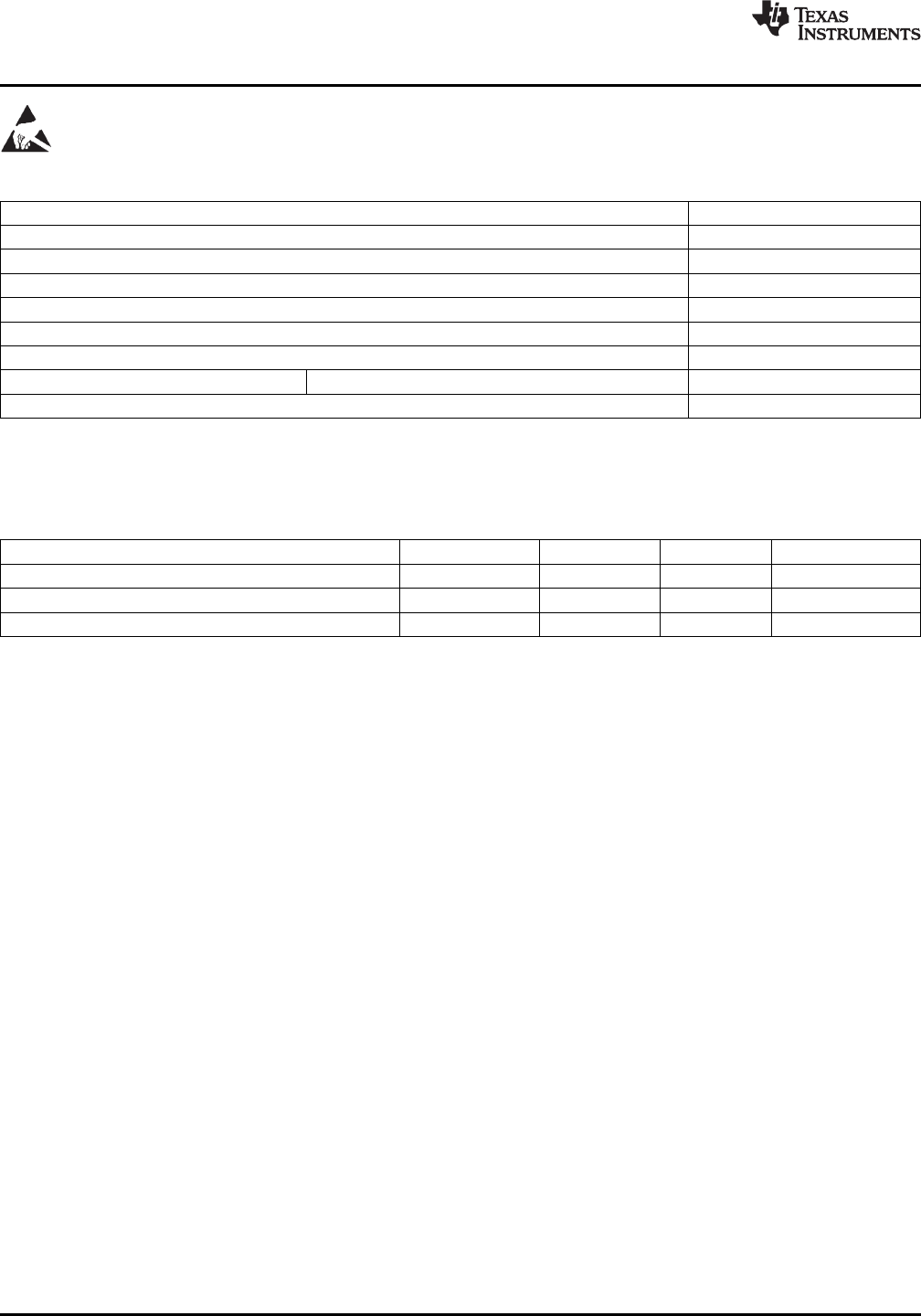
Absolute Maximum Ratings
(1)(2)
Supply Voltage (V
DD
) -0.5V to 4.0 V
LVCMOS Input Voltage -0.5V to (V
DD
+ 0.5) V
LVCMOS Output Voltage -0.5V to (V
DD
+ 0.5) V
CML Input/Output Voltage -0.5V to (V
DD
+ 0.5) V
Junction Temperature +125°C
Storage Temperature -65°C to +150°C
Lead Temp. (Soldering, 5 sec.) +260°C
ESD Rating HBM, 1.5 kΩ, 100 pF >8 kV
Thermal Resistance θ
JA
, No Airflow 33°C/W
(1) “Absolute Maximum Ratings” are the ratings beyond which the safety of the device cannot be ensured. They are not meant to imply that
the device should be operated at these limits.
(2) If Military/Aerospace specified devices are required, please contact the Texas Instruments Sales Office/Distributors for availability and
specifications.
Recommended Operating Conditions
(1)(2)
Min Typ Max Units
Supply Voltage (V
DD
to GND) 3.135 3.3 3.465 V
Supply Noise Tolerance (100 Hz to 50 MHz)
(3)
100 mVp-p
Ambient Temperature 0 25 +70 °C
(1) Typical parameters are measured at V
DD
= 3.3 V, T
A
= 25 °C. They are for reference purposes, and are not production-tested.
(2) Parameter is ensured by statistical analysis and/or design.
(3) Allowed supply noise (mVp-p sine wave) at typical condition.
4 Submit Documentation Feedback Copyright © 2009–2013, Texas Instruments Incorporated
Product Folder Links: DS34RT5110