
Datasheet


Table Of Contents
- FEATURES
- Applications
- DESCRIPTION
- Absolute Maximum Ratings
- Recommended Operating Conditions
- Electrical Characteristics
- Setup and Timing Diagrams
- Functional Description
- Application Information
- TYPICAL APPLICATION
- MULTIPLE HOP APPLICATION
- MATRIX SWITCH APPLICATION
- DUAL LINK APPLICATION
- DC AND AC COUPLED APPLICATIONS
- CABLE SELECTION AND INTER-PAIR SKEW
- 28 AWG STP (SHIELDED TWIST PAIRS) DVI / HDMI CABLES RECOMMENDED EQ SETTINGS
- 24 AWG UTP (LOW SKEW UNSHIELDED TWIST PAIRS) CABLES
- General Recommendations
- Typical Performance Characteristics as a Repeater
- Revision History
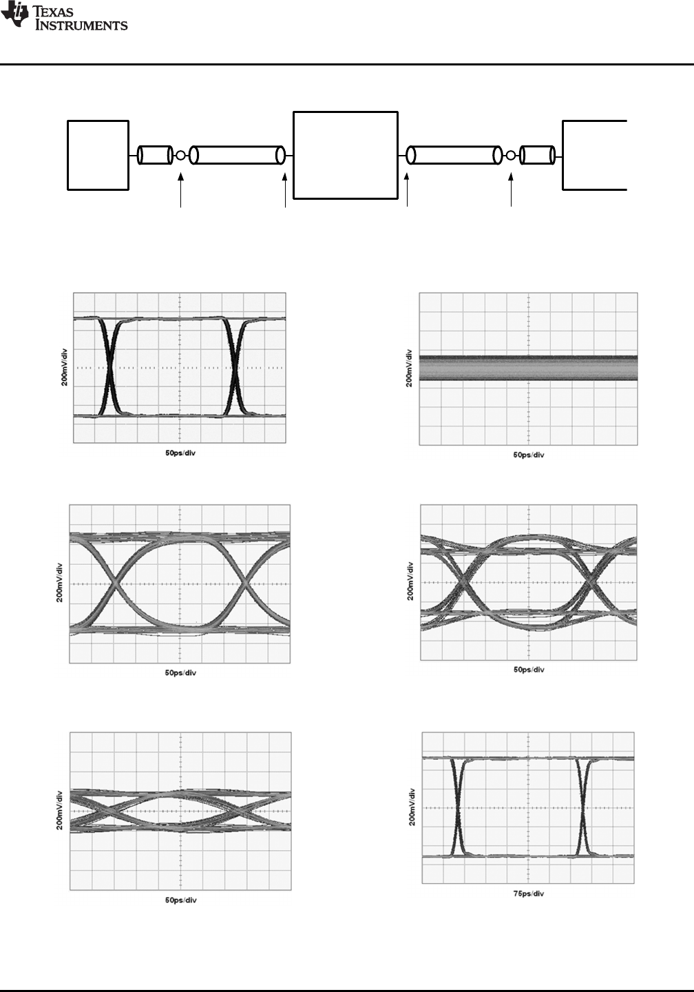
Pattern
Generator
TPA
TPB
TPD
Cable A
Coax Coax
Jitter
Test
Instrument
Cable B
TPC
DS34RT5110
DS34RT5110
www.ti.com
SNLS310G –MARCH 2009–REVISED APRIL 2013
Typical Performance Characteristics as a Repeater
Figure 16. Simplified Test Setup as a Single Repeater
Figure 17. System Source Eye Diagram at TPA Figure 18. Device Sink Eye Diagram at TPB
(3.4 Gbps) (3.4 Gbps, Cable A = 20m 28 AWG HDMI)
Figure 19. Device Source Eye Diagram at TPC Figure 20. Device Source Eye Diagram at TPC
(3.4 Gbps, Cable A = 20m 28 AWG HDMI, (3.4 Gbps, Cable A = 20m 28 AWG HDMI,
EQ = 0x05, BYPASS = 0, DE = 0dB) EQ = 0x05, BYPASS = 0, DE = -3dB)
Figure 21. System Sink Eye Diagram at TPD Figure 22. System Source Eye Diagram at TPA
(3.4 Gbps, Cable A = 20m 28 AWG HDMI, Cable B = 5m (2.25 Gbps)
28AWG HDMI, EQ = 0x05, BYPASS = 0, DE = -3dB)
Copyright © 2009–2013, Texas Instruments Incorporated Submit Documentation Feedback 17
Product Folder Links: DS34RT5110