
Datasheet


Table Of Contents
- FEATURES
- Applications
- DESCRIPTION
- Absolute Maximum Ratings
- Recommended Operating Conditions
- Electrical Characteristics
- Setup and Timing Diagrams
- Functional Description
- Application Information
- TYPICAL APPLICATION
- MULTIPLE HOP APPLICATION
- MATRIX SWITCH APPLICATION
- DUAL LINK APPLICATION
- DC AND AC COUPLED APPLICATIONS
- CABLE SELECTION AND INTER-PAIR SKEW
- 28 AWG STP (SHIELDED TWIST PAIRS) DVI / HDMI CABLES RECOMMENDED EQ SETTINGS
- 24 AWG UTP (LOW SKEW UNSHIELDED TWIST PAIRS) CABLES
- General Recommendations
- Typical Performance Characteristics as a Repeater
- Revision History
DES/Display
Processor
10.2 G DVI/HDMI Sink
5m 28 AWG DVI/HDMI Cable
DS34RT5110
DS34RT5110
DES/Display
Processor
10.2 G DVI/HDMI Sink
20m 28 AWG DVI/HDMI Cable
SER/A/V
Decoder
10.2 G DVI/HDMI Source
SER A/V
Decoder
10.2 G DVI/HDMI Source
20m 28 AWG DVI/HDMI Cable
DS34RT5110
DVI/HDMI Repeater
5m 28 AWG DVI/HDMI Cable
10.2 G DVI/HDMI Sink
DES/Display
Processor
10.2 G DVI/HDMI Source
SER/A/V
Decoder
DS34RT5110
SNLS310G –MARCH 2009–REVISED APRIL 2013
www.ti.com
AUTOMATIC ENABLE FEATURE
During normal operation (i.e. BYPASS pin is LOW), the DS34RT5110 can be configured to automatically enter
STANDBY mode, if the PLL of the DS34RT5110 is not locked. The STANDBY mode can be implemented by
connecting the LOCK DETECT (LOCK) pin to the external (LVCMOS) Enable (EN) pin. If the LOCK pin is
connected to the EN pin, a logic HIGH on the LOCK pin will enable the device; thus the DS34RT5110 will
automatically enter the ACTIVE state. If the PLL is unlocked, then the LOCK pin will be asserted LOW, causing
the aforementioned blocks to be placed in the STANDBY state.
APPLICATION INFORMATION
The DS34RT5110 is a DVI/HDMI video signal reconditioning device. The device conforms to DVI v1.0 and HDMI
v1.3a standards supporting up to 10.2 Gbps total throughput TMDS data for 1080p with 48 bit deep color depth.
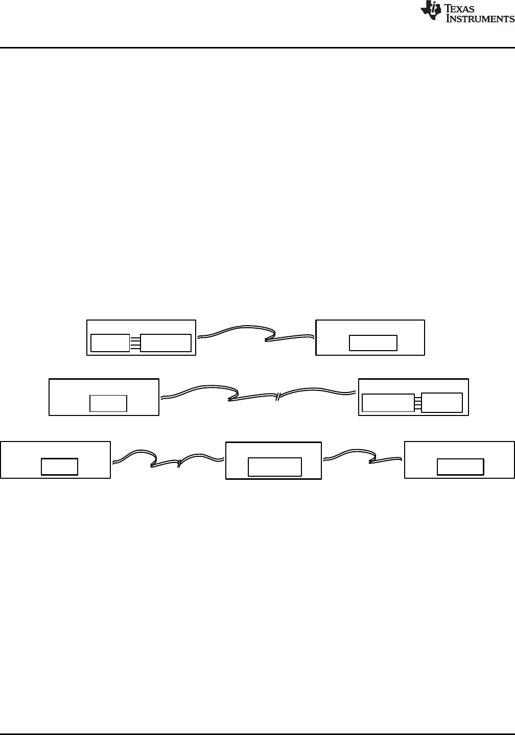
TYPICAL APPLICATION
In general, the DS34RT5110 in the default mode (MODE = L) is used as a DVI/HDMI source device, sink device,
or a repeater device, see Figure 8. As the source device, the output de-emphasis setting should be configured
based on the driving cable length. When used as the sink device, the levels of the equalization boost of the input
data channels should be optimized based on the receiving cable length. The DS34RT5110 can also be used as
a repeater in an external extender box with the equalization and de-emphasis level settings optimized to provide
the maximum cable reach.
Figure 8. Typical Application Diagram
MULTIPLE HOP APPLICATION
For DVI/HDMI home theater and professional studio systems with extensive lengths of cable, multi-hops with 2 or
more cascaded DS34RT5110 devices can be implemented as shown in Figure 9. In order to reach the maximum
cable length, the levels of the equalization and de-emphasis should be optimized for each individual hop. The
MODE pin(s) of the device at the first hop (using two hop application), or at the first and the second hops (using
three hop application shown in Figure 9) is recommended to be set HIGH to minimize the jitter accumulation in
multiple hops. The MODE pin of the device for the final hop should be set to a LOW state to clean up the clock
jitter, in order to drive the maximum cable length to the Sink.
12 Submit Documentation Feedback Copyright © 2009–2013, Texas Instruments Incorporated
Product Folder Links: DS34RT5110