
Datasheet


Table Of Contents
- FEATURES
- Applications
- DESCRIPTION
- Absolute Maximum Ratings
- Recommended Operating Conditions
- Electrical Characteristics
- Setup and Timing Diagrams
- Functional Description
- Application Information
- TYPICAL APPLICATION
- MULTIPLE HOP APPLICATION
- MATRIX SWITCH APPLICATION
- DUAL LINK APPLICATION
- DC AND AC COUPLED APPLICATIONS
- CABLE SELECTION AND INTER-PAIR SKEW
- 28 AWG STP (SHIELDED TWIST PAIRS) DVI / HDMI CABLES RECOMMENDED EQ SETTINGS
- 24 AWG UTP (LOW SKEW UNSHIELDED TWIST PAIRS) CABLES
- General Recommendations
- Typical Performance Characteristics as a Repeater
- Revision History
DS34RT5110
SNLS310G –MARCH 2009–REVISED APRIL 2013
www.ti.com
PHASE-LOCKED-LOCKED LOOP (PLL)
The clock channel has a high-performance PLL that creates a low jitter sampling clock for the clock and data
recovery units in the data channels. An external loop filter, composed of 2.2 nF (+ 5% tolerance) capacitor and a
3.3 kΩ (+ 5% tolerance) resistor in series, are required between the LFp and the LFn pins.
CLOCK-DATA RECOVERY UNIT (CDR)
Each TMDS data channel has a CDR that operates independently from other TMDS data channels. Each CDR
aligns the sampling clock edges by digitally interpolating the clock from PLL of the TMDS clock channel. The
device is designed to connect to DVI/HDMI compatible transmitter and receiver at any data rate between 250
Mbps to 3.4 Gbps. The loop bandwidth of the CDR is approximately baud_rate/1000, i.e. 2.25 MHz for 2.25 Gbps
data.
INPUT EQUALIZATION
The input data channel equalizers support eight programmable levels of equalization boost Table 1 by the EQ
pins (EQ [2:0]). The range of boost settings provided enables the DS34RT5110 to address a wide range of
transmission line path loss scenarios, enabling support for a variety of data rates and formats. See Application
Information for recommended EQ settings.
OUTPUT DE-EMPHASIS
De-emphasis is the conditioning function for use in compensating against backplane and cable transmission loss.
The DS34RT5110 provides four steps of de-emphasis ranging from 0, 3, 6 and 9 dB, user-selectable dependent
on the loss profile of output channels. Table 2 shows the De-emphasis control with default VO = 1000 mVp-p,
and Figure 7 shows a driver de-emphasis waveform.
OUTPUT VO CONTROL
Output differential voltage (VO) is controlled through VOD_CRL pin ties an external resistor to the ground as
shown in Table 3. Users should restrict the external resistor values used to be 12 kΩ to 24 kΩ. +5% tolerance is
recommended.
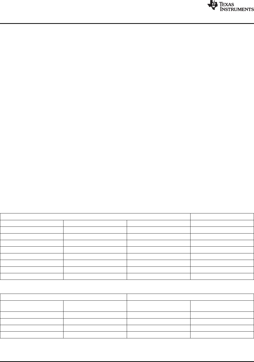
Table 1. Equalization Control
INPUTS RESULT
EQ2 EQ1 EQ0 Equalization in dB (1.7 GHz)
0 0 0 0 (default)
0 0 1 10
0 1 0 16
0 1 1 19
1 0 0 23
1 0 1 25
1 1 0 26
1 1 1 27
Table 2. De-Emphasis Control
INPUTS RESULT
VO De-Emphasis level in mVp-p
DE1 DE0 VO De-Emphasis in dB
(VODE w/VOD_CRL = 24 kΩ
0 0 1000 (default) 0 (default)
0 1 710 -3
1 0 500 -6
1 1 355 -9
10 Submit Documentation Feedback Copyright © 2009–2013, Texas Instruments Incorporated
Product Folder Links: DS34RT5110