
Datasheet


DS26LS32AC, DS26LS32C, DS26LS32M, DS26LS33M
www.ti.com
SNLS352C –MAY 1999–REVISED FEBRUARY 2013
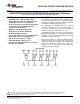
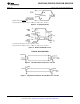
Diagram shown for ENABLE low.
Pulse generator for all pulses: Rate = 1.0 MHz; Z
O
= 50Ω; t
r
≤ 6 ns; t
f
≤ 6.0 ns.
Figure 4. Propagation Delay
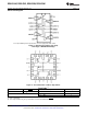
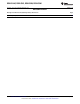
S1 and S2 of load circuit are closed except where shown.
Pulse generator for all pulses: Rate = 1.0 MHz; Z
O
= 50Ω; t
r
≤ 6 ns; t
f
≤ 6.0 ns.
Figure 5. Enable and Disable Times
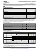
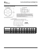
TYPICAL APPLICATIONS
Figure 6. Two-Wire Balanced Interface—RS-422
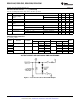
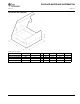
Figure 7. Single Wire with Driver Ground Reference—RS-423
Copyright © 1999–2013, Texas Instruments Incorporated Submit Documentation Feedback 5
Product Folder Links: DS26LS32AC DS26LS32C DS26LS32M DS26LS33M