
Datasheet


DS26LS32AC, DS26LS32C, DS26LS32M, DS26LS33M
SNLS352C –MAY 1999–REVISED FEBRUARY 2013
www.ti.com
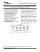
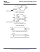
Connection Diagram
For Complete Military Product Specifications, refer to the appropriate SMD or MDS.
Figure 1. Dual-In-Line Package (Top View)
D Package or NFG0016E Package
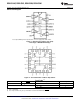
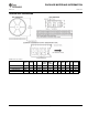
Figure 2. 20-Lead Ceramic Leadless Chip Carrier
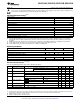
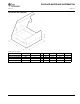
Truth Table
(1)
ENABLE ENABLE Input Output
0 1 X Hi-Z
See note below.
(2)
V
ID
≥ V
TH
(Max) 1
V
ID
≤ V
TH
(Min) 0
(1) Hi-Z = TRI-STATE
(2) Note: Input conditions may be any combination not defined for ENABLE and ENABLE .
2 Submit Documentation Feedback Copyright © 1999–2013, Texas Instruments Incorporated
Product Folder Links: DS26LS32AC DS26LS32C DS26LS32M DS26LS33M