
Datasheet


Table Of Contents
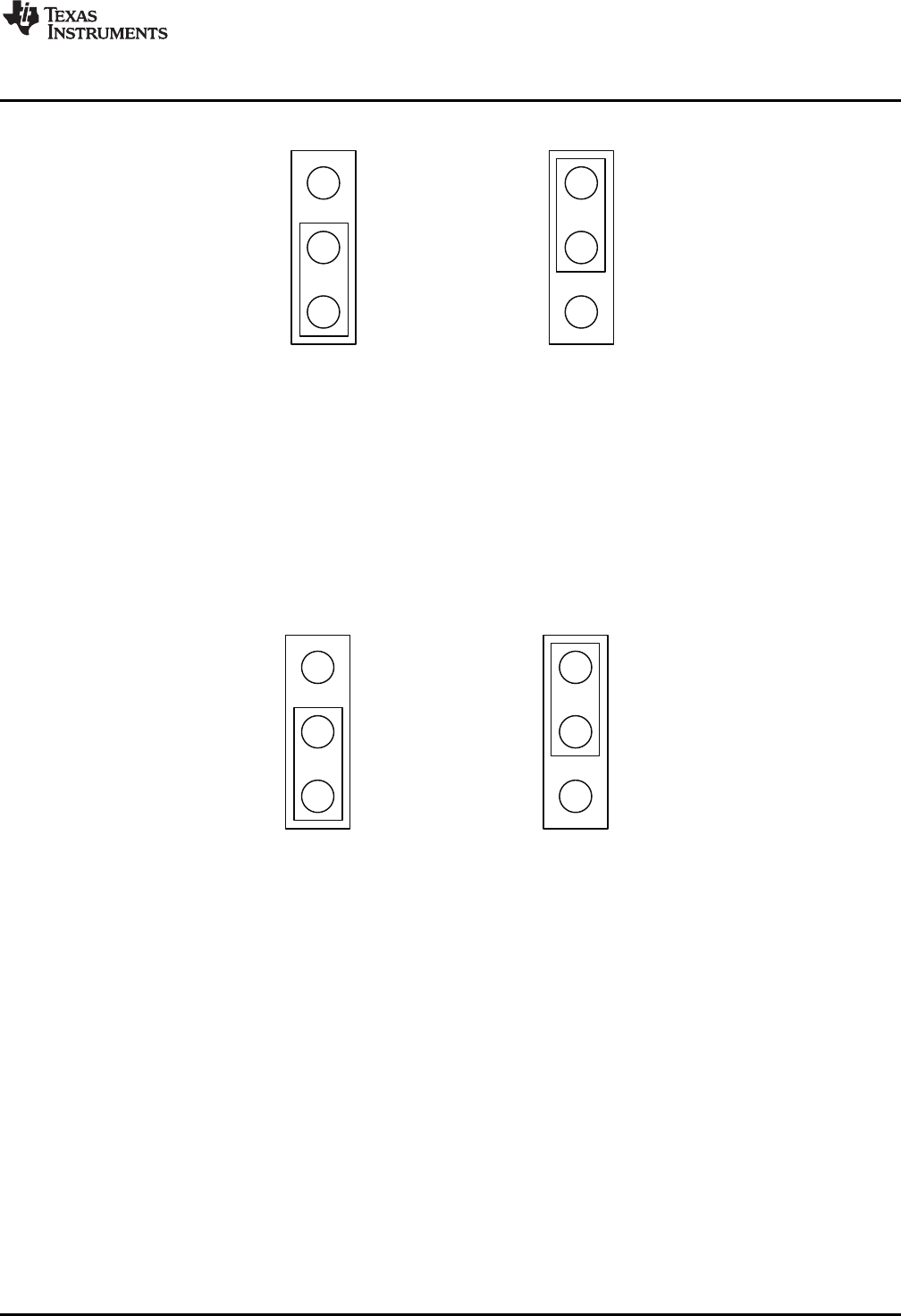
(a) (b)
1 1
From Pot
From DAC
To configure the AVREF select jumper:
(a) Use position JP2-1:2 to select the MSP430 DAC output (default).
(b) Use position JP2-2:3 to select the respective variable resistance
potentiometer. This jumper should not be left open as lack of
reference voltage on the device will minimize current sourcing
into the respective H Bridge, resulting in very poor motion or
no motion at all.
(a) (b)
1 1
From Pot
From DAC
To configure the DECAY select jumper:
(a) Use position JP3-1:2 to select the MSP430 GPIO functionality (default).
(b) Use position JP3-2:3 to select the respective variable resistance
potentiometer. Allowing the jumper to not be placed, will result in the
device operating under mixed decay mode.
www.ti.com
Block Diagram
1.3.1 AVREF Select Jumper (JP2)
Figure 1. AVREF Select Jumper Configuration
1.3.2 DECAY Select Jumper (JP3)
Figure 2. DECAY Select Jumper Configuration
1.4 Motor Outputs
There are two ways of connecting the DC motor into the CPG005_DRV88xx Evaluation Module: two pin
header (J4) or two position terminal block (J3). Although feasible, we do not recommend the connection of
any motor into the test clips as these are Kelvin connections and not rated for high current output.
3
SLVU410–April 2011 CPG005_DRV88xx Evaluation Modules
Submit Documentation Feedback
Copyright © 2011, Texas Instruments Incorporated